
Deconstructing the Electric Motor Control Wiring Diagram
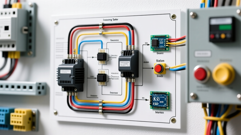
When designing or troubleshooting industrial automation systems, understanding a electric motor control wiring diagram requires a fundamental paradigm shift: you must mentally separate the high-voltage power circuit from the low-voltage control logic circuit. While the power circuit delivers the raw torque required to spin the rotor, the control circuit acts as the brain, dictating when, how, and in which direction that power is applied.
⚠️ CRITICAL SAFETY WARNING: Industrial 3-phase systems (230V–480V) carry lethal arc flash hazards. Always perform Lockout/Tagout (LOTO) and verify zero energy state with a CAT III/IV rated multimeter before opening any motor control center (MCC) or starter enclosure. Reference NFPA 70 (NEC) Article 430 for mandatory disconnecting means requirements.
In this comprehensive guide, we will dissect the anatomy of a 3-phase reversing motor starter, using a benchmark 5 HP, 460V AC induction motor. We will cover exact component selection, NEC-compliant wire sizing, interlocking logic, and real-world failure modes you won't find in basic textbook schematics.
Component Selection: The 2026 Industrial Benchmark
For a 5 HP motor operating at 460V, the Full Load Amps (FLA) is approximately 7.6A. To ensure longevity and withstand inrush currents (which can be 600% of FLA), we utilize a NEMA Size 2 or an equivalent heavy-duty IEC frame contactor. Here is a precise bill of materials (BOM) for a modern, reliable reversing assembly:
- Contactor (Forward & Reverse): Siemens Sirius 3RT2026-1AP0 (25A, 11kW @ 460V). Estimated cost: $85 each.
- Mechanical Interlock: Siemens 3RA2921-1AB. Estimated cost: $25.
- Thermal Overload Relay: Siemens 3RU2116-1KB0 (Adjustable 6.3A–9.0A). Estimated cost: $65.
- Control Transformer: Hammond 184T12 (480V Primary to 120V Secondary, 100VA). Estimated cost: $70.
- Control Fusing: Mersen ATMR5 (5A Primary) and ATMR2 (2A Secondary) Class CC fuses.
The Power Circuit: Phase Swapping for Reversal
The power circuit is responsible for routing the 3-phase supply (L1, L2, L3) to the motor terminals (T1, T2, T3). To reverse the direction of a 3-phase AC induction motor, you must swap any two of the three incoming power leads. In a standard reversing electric motor control wiring diagram, this is achieved using two separate contactors:
Forward Contactor (F) Wiring
The Forward contactor passes power straight through:
- L1 → T1
- L2 → T2
- L3 → T3
Reverse Contactor (R) Wiring
The Reverse contactor crosses the outer phases to invert the rotating magnetic field:
- L1 → T3 (Swapped)
- L2 → T2 (Straight)
- L3 → T1 (Swapped)
Expert Tip: Never attempt to swap phases on the load side (T-side) of a single contactor using a switch. The arc flash risk and potential for phase-to-phase short circuits during switching are unacceptably high. Always use dual contactors with rigid busbar crossovers.
The Control Circuit: Logic, Pushbuttons, and Interlocking
The control circuit typically operates at 120VAC, stepped down from the 480V mains via the Hammond control transformer. This lower voltage protects the operator at the pushbutton station and extends the life of the contactor coils.
The Crucial Role of Interlocking
If both the Forward and Reverse contactors close simultaneously, L1 and L3 will short together through the contactor busbars, resulting in a catastrophic phase-to-phase fault and explosive arc flash. To prevent this, the diagram mandates dual interlocking:
- Mechanical Interlock: A physical lever (Siemens 3RA2921-1AB) bolted between the two contactors that physically blocks the armature of one contactor from pulling in if the other is already engaged.
- Electrical Interlock: Normally Closed (NC) auxiliary contacts wired in series with the opposing coil. The Forward coil circuit is routed through the Reverse contactor's NC auxiliary contact, and vice versa. If the Reverse contactor is energized, its NC contact opens, physically cutting the 120VAC path to the Forward coil.
Step-by-Step Control Wiring Sequence
According to standard EC&M motor control logic principles, the 120VAC control circuit flows as follows:
- Line 1 (Hot): From the secondary side of the control transformer (X1), routed through the 2A secondary fuse.
- Stop Circuit: The hot leg passes through the Normally Closed (NC) Stop pushbutton.
- Overload Protection: The circuit then passes through the NC auxiliary contact on the thermal overload relay (3RU2116). If the motor overheats, this contact drops out, killing power to all coils.
- Directional Branching: The circuit splits into two parallel branches for the Forward and Reverse Start pushbuttons (Normally Open).
- Electrical Interlocks: Before reaching the Forward Start button, the wire passes through the Reverse NC auxiliary contact (and vice versa for the Reverse branch).
- Coil Energization: Pressing the Forward Start button sends 120VAC to the Forward coil (A1 to A2). The contactor pulls in.
- Seal-In (Holding) Circuit: A Normally Open (NO) auxiliary contact on the Forward contactor, wired in parallel with the Start button, closes to maintain power to the coil once the operator releases the button.
NEC Compliance: Wire Sizing and Overload Protection
Sizing conductors for motor circuits does not follow standard branch circuit rules. Per NEC Article 430, motor conductors must be sized at 125% of the motor's Full Load Amps (FLA) as listed in Table 430.250, not the nameplate FLA.
| Parameter | Calculation / NEC Rule | 5 HP @ 460V Specification |
|---|---|---|
| Table 430.250 FLA | Base Value from NEC Table | 7.6 Amps |
| Conductor Ampacity (Min) | 7.6A × 1.25 (NEC 430.22) | 9.5 Amps |
| Recommended Wire Gauge | THHN Copper (75°C Column) | 14 AWG (Min), 12 AWG (Preferred for V-drop) |
| Thermal Overload Setting | Nameplate FLA × 1.15 (SF) | Set to ~8.7A on the 3RU2116 dial |
| Short Circuit Protection | Time-Delay Fuse (Max 175%) | 15A Dual-Element Time-Delay (e.g., Fusetron) |
Advanced Troubleshooting Matrix
When a reversing starter fails, technicians often waste hours tracing wires. Use this diagnostic matrix based on Fluke's advanced motor troubleshooting methodologies to isolate faults rapidly.
| Symptom | Probable Root Cause | Diagnostic Action |
|---|---|---|
| Motor hums but won't start (Forward) | Single-phasing or failed Forward coil | Check voltage at T1, T2, T3 under load. Measure coil resistance (A1-A2); expect 15-30 ohms. |
| Motor runs Forward, stalls on Reverse | Failed electrical interlock or Reverse Start PB | Verify continuity across Reverse NC interlock while Forward is manually depressed. Check Reverse PB contacts. |
| Contactor chatters loudly | Low control voltage or shading coil failure | Measure voltage at A1-A2 during pull-in. If < 85% of nominal (102VAC), check control transformer sizing. |
| Overload trips immediately on start | Overload dial set to FLA instead of 115% SF | Verify dial setting. Check for mechanical binding on the driven load causing high starting torque. |
Real-World Failure Modes and Edge Cases
Contact Welding Due to High Inertia
A common edge case in industrial environments occurs when reversing a high-inertia load (like a large centrifugal fan or flywheel) before it has completely stopped. This technique, known as 'plugging' or 'reverse-current braking', generates immense heat and mechanical stress. If the arc generated during contactor opening sustains too long, the silver-alloy contacts can melt and weld together. If the Forward contacts weld shut, and the operator subsequently commands Reverse, the mechanical interlock will prevent the Reverse contactor from closing, but the motor will continue to run Forward. Solution: Implement a zero-speed sensor or use a Variable Frequency Drive (VFD) with dynamic braking for high-inertia applications.
Control Transformer Saturation
If you add indicator lights, PLC inputs, or auxiliary relays to the control circuit without recalculating the VA burden, the 100VA control transformer may saturate during contactor inrush. A contactor coil can draw 5 to 10 times its sealed VA during the initial pull-in. If the voltage drops below 80% during this millisecond window, the contactor will chatter, leading to rapid coil burnout. Always sum the sealed VA of all continuous loads, add the inrush VA of the largest contactor, and multiply by 1.2 to size the control transformer.