
The Electrical Demands of Boss Snowplows
Installing or troubleshooting a Boss snowplow requires a deep understanding of high-amperage DC power distribution. Whether you are rigging a standard straight blade or a heavy-duty Boss V-DXT, the hydraulic power pack motor can draw between 120 and 180 amps under peak load (such as stacking dense, wet snow). If your panel, breakers, and wire gauges are not sized correctly, you risk severe voltage drop, melted harnesses, or catastrophic pump failure.
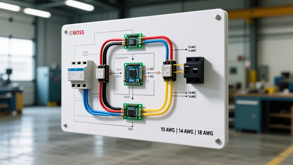
This guide decodes the wiring diagram for Boss plow systems from a panel and breaker perspective, ensuring your truck's electrical system can handle the brutal demands of commercial snow removal. As of 2026, Boss has fully transitioned to their FleetFlex multiplex architecture on models like the Xtreme and V-DXT, which fundamentally changes how control circuits are protected and routed compared to legacy 11-pin relay systems.
Breaker and Fuse Sizing Matrix
Proper overcurrent protection is non-negotiable. According to guidelines from the National Truck Equipment Association (NTEA), auxiliary equipment on work trucks must be fused independently of the chassis OEM harness. Below is the definitive breaker sizing matrix for modern Boss plow installations.
| Circuit Function | Wire Gauge (SAE J1128) | Breaker / Fuse Size | Breaker Type |
|---|---|---|---|
| Main Power Feed (Battery to Solenoid) | 1/0 AWG (or 2 AWG for runs < 10ft) | 150 Amp | Type 1 (Auto-Reset) or Class T Fuse |
| Control Power (Cab to Plow Harness) | 10 AWG | 30 Amp | Manual-Reset (Pop-out) |
| Lighting & Markers | 14 AWG | 15 Amp | Type 2 (Modified Auto-Reset) |
Main Power Feed: The 150A Circuit
The main power cable runs directly from the truck's battery positive terminal to the plow's main solenoid or power pack. You must use a minimum of 2 AWG copper wire, though 1/0 AWG is highly recommended for full-size trucks where the battery is located far from the front bumper mount. A 150-amp auto-reset circuit breaker (often a Bussmann or Littelfuse heavy-duty stud-mounted unit, costing roughly $35-$50) must be installed within 18 inches of the battery terminal to protect the entire cable run from a dead short.
Control and Lighting Circuits
The control circuit powers the cab controller and the plow-side relay pack (or multiplex module). A 30-amp manual-reset breaker is used here. We specify manual-reset for the control circuit because if a short occurs in the 13-pin harness, you do not want the system automatically re-energizing and potentially causing a fire while the operator is in the cab. Lighting circuits utilize standard 15A auto-reset breakers integrated into the truck-side lighting harness.
Standard Relay vs. FleetFlex Multiplex Systems
When reading a wiring diagram for Boss plow setups, you will encounter one of two primary architectures. Understanding the difference is critical for panel layout and troubleshooting.
Expert Insight: Legacy Boss systems used an 11-pin connector with individual wires for every solenoid function (lift, drop, left, right). Modern FleetFlex systems use a 13-pin connector and solid-state multiplexing. This reduces the cab-to-plow wiring from over a dozen heavy wires down to just power, ground, and two CAN-bus communication lines.
FleetFlex Panel Requirements and Connector Care
Because FleetFlex relies on solid-state relays and microcontrollers housed in the plow-side power pack, the truck-side panel requirements are actually simpler, but more sensitive to voltage drops. The multiplex module requires a clean, stable 12V reference. If your 10 AWG control wire suffers from voltage drop due to a corroded inline fuse holder, the FleetFlex module will throw a communication error code on the cab display, even if the main 150A hydraulic circuit is perfectly fine.
Furthermore, the 13-pin connector is the lifeline of the FleetFlex system. Road salt and moisture are constant threats. At the start of every 2026 winter season, disconnect the 13-pin plug, inspect the pins for green copper oxide, and treat them with a high-quality contact cleaner like DeoxIT D5. Do not use standard WD-40, as it leaves a residue that attracts dust and increases contact resistance over time.
Step-by-Step Grounding & Panel Routing
According to official Boss Snowplows literature, over 70% of plow electrical failures are ground-related. Do not rely on the truck's chassis or the plow mounting frame for your primary electrical ground.
- Engine Block Grounding: Run a dedicated 2 AWG or 1/0 AWG ground cable from the negative terminal of the truck battery (or the main negative busbar) directly to a clean, bare-metal stud on the engine block. The plow draws current from the alternator; grounding to the chassis forces current through the engine-to-chassis strap, which is not rated for 150A continuous duty.
- Plow Frame Ground: Attach the plow ground wire to the truck frame using a star washer to bite through paint and powder coating. Apply dielectric grease over the terminal after torquing to 25 ft-lbs to prevent winter road salt corrosion.
- Breaker Panel Placement: Mount your main 150A breaker and 30A control breaker in a sealed, weatherproof fuse block (like a Blue Sea Systems heavy-duty stud box) high up in the engine bay, away from direct road spray and heat from the exhaust manifold.
Advanced Troubleshooting: Voltage Drop Testing
If your Boss plow motor bogs down or the controller resets when angling the blade, do not immediately replace the pump. Perform a voltage drop test across your breakers and panel connections.
- Set your multimeter to DC Volts.
- Place the red probe on the battery side of the 150A breaker, and the black probe on the solenoid side.
- Activate the plow (lift or angle) to draw maximum current.
- Read the drop: A healthy breaker and cable run will show less than 0.2V drop. If you read 0.5V or higher, the internal contacts of the breaker are pitted, or the lug crimps on your 1/0 AWG cable are failing due to strand corrosion.
Replacing a pitted 150A breaker ($40) takes ten minutes and can restore full hydraulic speed, saving you from buying a $600 replacement power pack motor. If the voltage drop is occurring across the entire system, your truck's OEM alternator may be undersized. Upgrading to a high-output 250A alternator (such as a Leece-Neville or Denso unit, typically costing $350-$500 installed) is a common necessity for modern trucks running FleetFlex plows alongside LED light bars and heated seats.
Frequently Asked Questions
Can I use an ANL fuse instead of a 150A circuit breaker?
Yes, a 150A Class T or ANL fuse is acceptable and often preferred by fleet managers because fuses do not suffer from internal contact pitting over time like auto-reset breakers. However, you must carry spare fuses in the cab. If an ANL fuse blows in a storm, you cannot reset it; you must replace it to restore plow function.
Why does my Boss plow controller display a 'Low Voltage' warning?
The FleetFlex system monitors input voltage continuously. If the alternator cannot keep up with the 150A draw plus the truck's OEM accessories, system voltage drops below 11.5V, triggering the warning. Ensuring your SAE standardized wiring is free of corrosion and upgrading your charging system will resolve this.
What is the torque spec for the main solenoid lugs?
Typically, the 3/8-inch studs on standard Boss heavy-duty solenoids require 10 to 12 ft-lbs. Over-torquing can snap the stud or crack the bakelite housing, leading to moisture ingress and internal arcing, which will destroy the solenoid and potentially weld the contacts shut.