
The Stakes of Non-Compliant Trailer Wiring
When wiring a boat trailer, utility trailer, or car hauler, relying on a generic internet schematic can lead to catastrophic failures. A proper 5 pin wiring diagram for trailer applications goes far beyond simply matching wire colors; it requires strict adherence to Department of Transportation (DOT) regulations and Society of Automotive Engineers (SAE) standards. According to the Federal Motor Carrier Safety Administration (FMCSA), lighting and brake system failures remain a top cause of out-of-service (OOS) violations during commercial inspections, and the same physics apply to consumer-grade trailers. Improper wire gauge sizing leads to voltage drop, resulting in dim tail lights that fail to meet FMVSS 108 luminosity requirements, while inadequate grounding can cause surge brake lockouts to fail when reversing. This guide provides a code-compliant, safety-first approach to 5-way flat trailer wiring.
Standard 5-Way Flat Pinout & FMVSS 108 Alignment
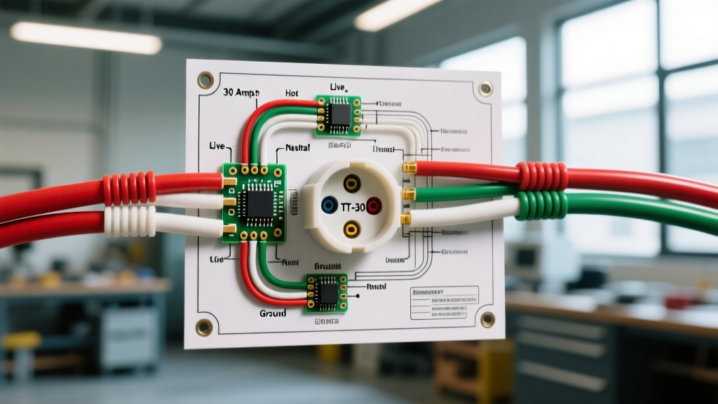
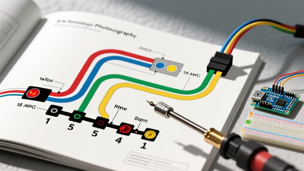
The 5-way flat connector adds a crucial fifth circuit to the standard 4-way setup. This auxiliary circuit is almost exclusively used to power a reverse lockout solenoid on surge brake couplers, preventing the brakes from engaging when the tow vehicle is placed in reverse. Below is the industry-standard pinout mapped to DOT compliance requirements.
| Pin Position | Wire Color | Function | SAE / DOT Compliance Note |
|---|---|---|---|
| 1 (Ground) | White | Chassis Ground Return | Must be grounded to clean, bare metal. FMVSS 108 requires independent grounding for certain trailer classes. |
| 2 (Tail) | Brown | Tail / Running Lights | Must illuminate all clearance, marker, and license plate lights. Minimum 2 candela for tail lamps. |
| 3 (Left) | Yellow | Left Turn / Stop Lamp | Combined stop/turn circuit. Must flash at 60-120 cycles per minute per FMVSS 108. |
| 4 (Right) | Green | Right Turn / Stop Lamp | Combined stop/turn circuit. Requires dedicated 12V feed from tow vehicle BCM or converter. |
| 5 (Aux) | Blue | Reverse / Brake Lockout | Activates only when tow vehicle is in reverse. Powers 12V DC solenoid (typically 5-8 amp draw). |
SAE J1128 Wire Gauge Sizing & Voltage Drop Mitigation
The most common code violation in DIY trailer wiring is the use of 16 AWG wire for the entire harness. While 16 AWG is sufficient for low-draw LED marker lights, it is a severe fire hazard and functional failure point for the auxiliary 5th pin (brake lockout) and long-run tail light circuits. Under SAE J1128 standards, low-tension primary cable must be sized based on continuous amperage and total circuit length to prevent excessive voltage drop.
For a 12V DC trailer system, a voltage drop exceeding 5% (0.6V) can cause solenoid chatter or failure to disengage the surge brakes. Always use cross-linked polyethylene wire (GXL or TXL type), which features a thinner insulation wall for better flexibility and higher temperature resistance (up to 125°C) compared to standard PVC wire.
Wire Gauge Selection Matrix (12V DC System)
| Total Harness Length (One Way) | Lighting Circuits (LED) | Lighting Circuits (Incandescent) | Pin 5 Aux / Brake Lockout |
|---|---|---|---|
| Under 10 Feet | 16 AWG | 14 AWG | 12 AWG |
| 10 to 20 Feet | 14 AWG | 12 AWG | 10 AWG |
| 20 to 30 Feet | 12 AWG | 10 AWG | 10 AWG |
| Over 30 Feet | 10 AWG | 10 AWG | 8 AWG |
Pro Tip: If you are wiring a 25-foot boat trailer with a Kodiak 71-5 reverse lockout solenoid (which draws roughly 6 amps under load), running 12 AWG GXL wire for the blue auxiliary circuit ensures the solenoid receives a full 11.4V+ at the coupler, guaranteeing reliable brake disengagement.
The 5th Pin: Reverse Lockout Solenoids & Surge Brakes
The defining feature of the 5 pin wiring diagram for trailer setups is the blue auxiliary wire. Unlike electric-over-hydraulic (EOH) brake systems that require a dedicated brake controller and 7-way connector, surge brake trailers rely on a mechanical hydraulic coupler. When you reverse, the coupler compresses, applying the brakes. To prevent this, a 12V DC solenoid is installed on the master cylinder to block hydraulic fluid flow during reverse maneuvers.
Wiring the Lockout Solenoid Safely
- Power Source: The blue wire from the 5-way flat connector routes to the reverse light circuit of the tow vehicle. When the transmission shifts into reverse, 12V is sent down the blue wire.
- Solenoid Connection: Connect the blue wire to one terminal of the lockout solenoid (e.g., Tie Down Engineering 11000 or Dexter DX7.5). Polarity generally does not matter on standard DC solenoids, but verify the manufacturer spec.
- Solenoid Ground: The second solenoid terminal must be grounded directly to the trailer tongue using a 12 AWG wire and a ring terminal. Do not rely on the solenoid casing to ground through the coupler, as paint and rust will interrupt the circuit.
- Overcurrent Protection: Install an inline 10A ATC fuse on the blue wire within 12 inches of the 5-way plug. If the solenoid shorts out due to water intrusion, this prevents the tow vehicle's reverse light circuit from frying.
Bypassing the 'White Wire Trap' for Chassis Grounding
A pervasive myth in trailer wiring is that the white ground wire from the 4-way or 5-way plug provides sufficient grounding for all trailer lights and accessories. In reality, the white wire is simply the ground return path back to the tow vehicle. Relying solely on the hitch ball for grounding is a massive safety risk; a rusty hitch or bouncing connection will instantly sever the ground path, causing lights to cross-feed (e.g., stepping on the brake causes the running lights to dim and the turn signals to illuminate).
Code-compliant wiring dictates that every light fixture must be grounded locally to the trailer chassis. If you are using LED trailer lights with a two-wire pigtail (power and ground), the ground wire must be terminated with a star washer and a self-tapping screw directly into bare, unpainted steel or aluminum. For aluminum trailers, use a dielectric barrier and ensure you are grounding to the main structural frame, not just a bolted-on crossmember. According to FMCSA brake system regulations, any electrical component actuating or interacting with brake mechanisms must have a dedicated, redundant ground path independent of the lighting harness.
Environmental Sealing: Beyond Electrical Tape
Trailer wiring operates in one of the most hostile electrical environments possible: submerged in water (boat ramps), blasted with road salt, and subjected to extreme vibration. Standard vinyl electrical tape is strictly prohibited for outdoor, submersible, or undercarriage splices. It will unspit within weeks due to UV degradation and temperature cycling.
- Adhesive Heat Shrink: Use marine-grade, dual-wall heat shrink tubing with an internal polyamide adhesive lining (such as 3M MDT-300). When heated, the inner wall melts and seals the wire strands, creating a 100% waterproof, strain-relieved connection.
- Dielectric Grease: Apply a high-quality silicone dielectric grease (like Permatex 22058) to the pins of the 5-way flat connector. This displaces moisture and prevents galvanic corrosion between the brass pins and the tow vehicle's socket.
- Loom and Clipping: Route all wiring through split loom tubing or corrugated conduit. Secure the harness every 18 inches using UV-resistant nylon zip ties or metal P-clips with rubber cushions. Never use metal screws to secure wire bundles directly, as vibration will eventually cut through the insulation and cause a dead short.
Troubleshooting Common DOT Inspection Failures
Even with a perfect 5 pin wiring diagram for trailer execution, environmental wear can introduce faults. Use this checklist to diagnose common compliance failures:
- Brakes Engage in Reverse: The 5th pin (blue) is not receiving 12V. Check the inline ATC fuse, test for voltage at the trailer plug with the tow vehicle in reverse (parking brake set), and verify the solenoid ground wire is not corroded.
- Dim or Flickering Running Lights: Indicates severe voltage drop. Upgrade the brown wire from 16 AWG to 12 AWG, or check for water intrusion inside the light housings causing micro-shorts.
- Turn Signal Hyper-Flashing: The tow vehicle's BCM (Body Control Module) detects a low-draw condition. If you recently upgraded to LED trailer lights, you must install a CANbus load resistor or an LED-specific flasher relay in the tow vehicle to simulate the resistance of incandescent bulbs.
- Lights Work Only When Hitch is Moved: The trailer is grounding through the hitch ball instead of the white wire. Clean the hitch ball, clean the coupler, and run a dedicated 10 AWG ground wire from the trailer tongue directly to the tow vehicle's frame near the plug.
Safety Directive: Never attempt to 'jump' the 5th pin to a constant 12V source to test the brake lockout. Leaving the surge brakes permanently disabled while driving forward violates federal safety standards and will result in a total loss of trailer braking capacity during a panic stop. The 5th pin must only be energized by the reverse light circuit.
By treating your 5-way flat wiring harness as a critical safety system rather than an afterthought, you ensure compliance with federal regulations, protect your tow vehicle's sensitive electronics, and guarantee that your trailer's lighting and braking systems perform flawlessly under load.