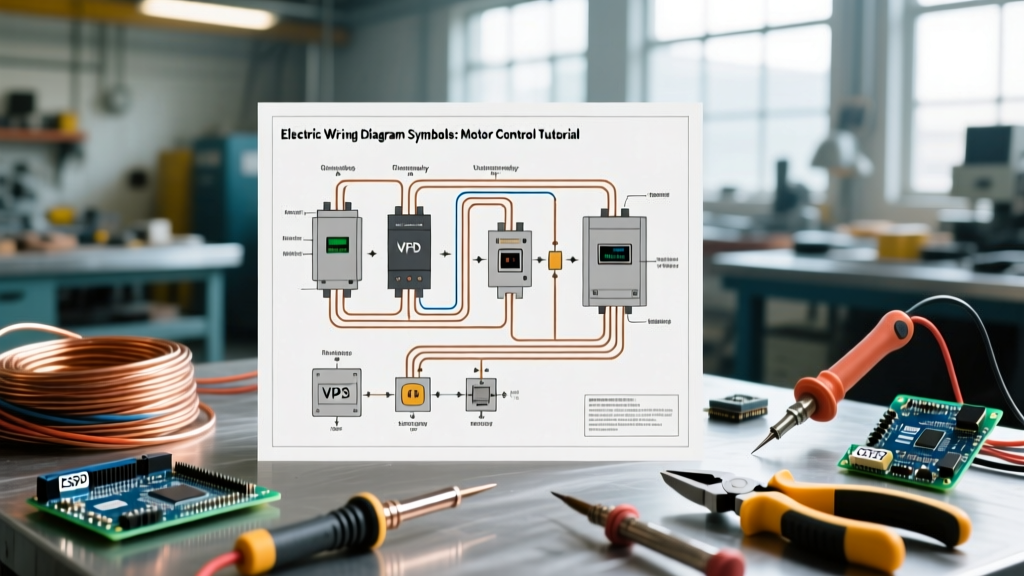

The Divide: Power vs. Control Circuits in Motor Wiring
Wiring an industrial or commercial electric motor extends far beyond simply terminating three phases and a ground. To safely commission a 5HP 3-phase induction motor or integrate a Variable Frequency Drive (VFD), you must fluently read schematics. Misinterpreting electric wiring diagram symbols is the leading cause of blown control fuses, welded contactor contacts, and catastrophic VFD failures.
Every motor schematic is divided into two distinct sections:
- The Power Circuit: The high-current path from the main disconnect, through fuses, contactors, and overload heaters, directly to the motor terminals (T1, T2, T3). Wire gauge here is dictated by the motor's Full Load Amps (FLA) and NEC Article 430.
- The Control Circuit: The low-current logic path (often 24VDC or 120VAC) that dictates when the power circuit engages. This includes pushbuttons, limit switches, PLC outputs, and contactor coils.
Standard Electric Wiring Diagram Symbols: NEMA vs. IEC
Before tracing a single wire, you must identify the drafting standard used by the panel builder. In North America, legacy systems often use NEMA (National Electrical Manufacturers Association) symbols, while modern global equipment and NEMA ICS standards increasingly align with IEC (International Electrotechnical Commission) symbols.
| Component | NEMA Symbol Description | IEC Symbol Description | Common Terminal Designations |
|---|---|---|---|
| Motor (3-Phase) | Circle with 'M' and 3 leads | Circle with 'M' or '3~' inside | U, V, W (IEC) or T1, T2, T3 (NEMA) |
| Contactor Coil | Circle or rectangle with 'M' or 'CR' | Rectangle with 'KM' or 'K' | A1 (Positive/Hot), A2 (Negative/Neutral) |
| Thermal Overload | Heater symbol in series with motor | Rectangle with thermal curve line | 95-96 (NC Trip Contact) |
| Pushbutton (NO) | Lines with a break and push actuator | Similar, often with 'I' or 'O' markers | 13-14 (NO), 21-22 (NC) |
Decoding Motor Starter Components
Understanding the specific terminal numbering system is where theoretical symbol knowledge translates into practical wiring skills. Let us break down the core components of a Direct-On-Line (DOL) motor starter.
Contactors and Auxiliary Contacts
A contactor is the heavy-duty relay that switches the motor's power. Take the widely used Schneider Electric TeSys Deca LC1D40 (a 40A IEC contactor). The main power contacts are labeled L1, L2, L3 on the line side and T1, T2, T3 on the load side. However, the control circuit relies on auxiliary contacts mounted on the side or front of the contactor.
- 13 and 14: Designates a Normally Open (NO) auxiliary contact. This is critical for the "seal-in" or "latching" circuit, which keeps the contactor energized after the operator releases the momentary start pushbutton.
- 21 and 22: Designates a Normally Closed (NC) auxiliary contact. This is used for electrical interlocking in reversing circuits.
Overload Relays (OL)
While fuses protect against short circuits, overload relays protect the motor from sustained overcurrent (e.g., a jammed conveyor belt). Modern electronic overloads like the Allen-Bradley 193-EIO feature a trip contact that must be wired into the control logic. The standard IEC designation for the NC trip contact is 95 and 96. If the motor draws excessive current, the 95-96 contact opens, breaking the circuit to the A1/A2 coil and dropping out the contactor.
Expert Tip: Never wire the overload 95-96 NC contact in parallel with the stop button. It must be in series with the entire control logic so that a thermal trip completely de-energizes the contactor coil, preventing automatic restart when the bimetallic strip cools and resets.
Practical Application: Wiring a 3-Phase Reversing Motor
Reversing a 3-phase AC motor requires swapping any two power leads (e.g., L1 and L3). A reversing starter uses two contactors: one for Forward (F) and one for Reverse (R). Reading the electric wiring diagram symbols for this circuit reveals a critical safety mechanism: interlocking.
- Power Circuit Interlock: The diagram will show the load side of the F contactor crossing two phases before terminating at the overload relay. If both contactors close simultaneously, it creates a dead phase-to-phase short circuit, resulting in an arc flash.
- Control Circuit Electrical Interlock: Trace the control logic. The wire feeding the Forward coil (F) will pass through the NC auxiliary contact (21-22) of the Reverse contactor (R). This ensures that if R is energized, the F coil circuit is physically broken.
- Mechanical Interlock: While not always drawn as a distinct electrical symbol, schematics often include a dashed line between the two contactor coils indicating a physical mechanical interlock block installed between them.
VFD Control Wiring Symbols and Terminals
Variable Frequency Drives (VFDs) replace traditional contactors in applications requiring speed control or soft starting. When wiring a drive like the Yaskawa A1000 or Allen-Bradley PowerFlex 525, the schematic symbols shift from discrete relays to digital logic.
Sink vs. Source Logic
VFD schematics will feature a jumper or switch symbol indicating Sink/Source configuration. This dictates how the 24VDC control power flows:
- Source Logic (PNP): The VFD provides the +24VDC. The switch (pushbutton or PLC transistor) connects the digital input (DI) to the Signal Common (SC or 0V).
- Sink Logic (NPN): The switch provides the +24VDC to the digital input, and the current flows through the VFD's internal optocoupler to ground.
Always verify the schematic symbols for the I/O configuration before applying power. Miswiring a 24V source into a sinking input can instantly destroy the drive's internal optocouplers.
Analog and Digital I/O Symbols
Look for specific terminal designations on the VFD block diagram:
- S1, S2, S3...: Digital Inputs (e.g., S1 = Run Forward, S2 = Run Reverse).
- FS / FC: Frequency Signal / Frequency Common (used for 0-10VDC speed reference).
- AM / AC: Analog Monitor output (e.g., 0-10V output proportional to motor RPM).
Troubleshooting Symbol Misinterpretations
Even seasoned electricians make errors when translating complex schematics into physical panel wiring. Here are the most common edge cases and failure modes related to symbol misreading:
The "Ghost" Seal-In Circuit
The Error: Wiring the NO auxiliary contact (13-14) in series with the start button instead of in parallel.
The Symptom: The motor only runs while the operator physically holds the start pushbutton. The moment they release it, the motor stops.
The Fix: The schematic shows the 13-14 contact branching off before the start button and reconnecting after it. This parallel path "seals in" the current flow once the coil energizes and closes the 13-14 contact.
Overlooking Control Transformer Sizing
Schematics often show a control transformer stepping down 480VAC to 120VAC. If the diagram symbols indicate multiple contactor coils, timers, and PLC relay outputs on the secondary side, you must calculate the total inrush VA. A standard 50VA transformer will sag and drop out the contactor if you simultaneously energize three large contactors with high inrush currents. Always upgrade to a 150VA or 250VA transformer for multi-starter panels.
Safety and Code Compliance
When interpreting and executing motor wiring diagrams, adherence to the National Electrical Code (NEC) and OSHA electrical safety standards is non-negotiable. Specifically, NEC Article 430 dictates that motor branch circuit conductors must be sized at 125% of the motor's Full Load Current (FLC), while control circuit wiring must adhere to Article 430.72, typically requiring 14 AWG copper for control circuits protected by standard overcurrent devices. Always verify the specific diagram symbols against the physical equipment nameplates before terminating a single wire.