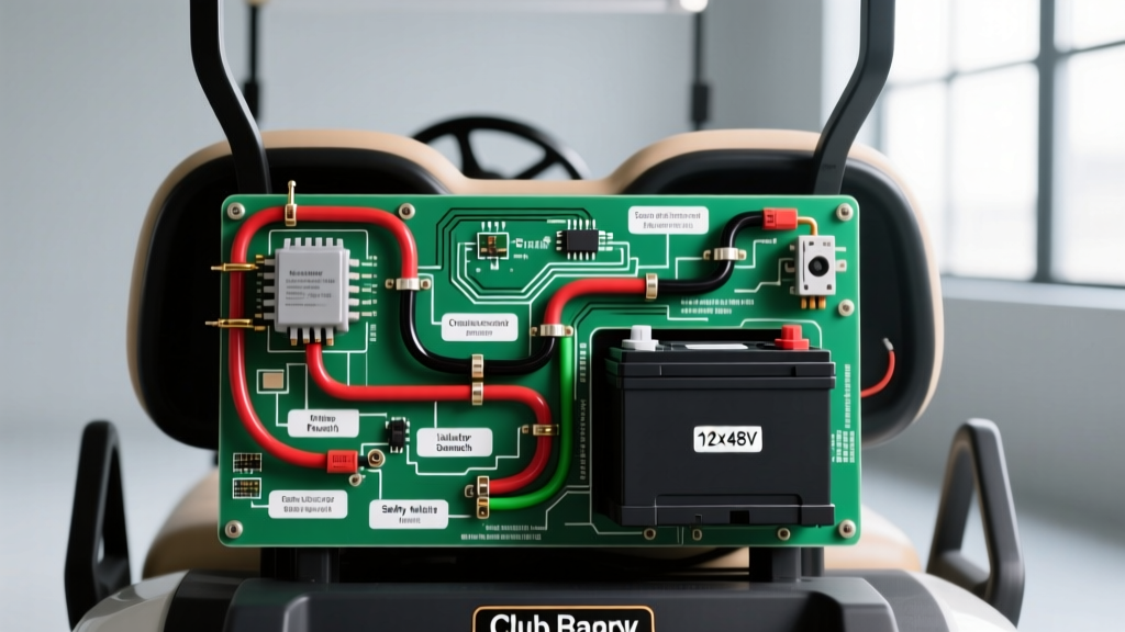

The Hidden Dangers of High-Amp 48V Golf Cart Systems
When enthusiasts and fleet mechanics pull up a wiring diagram for Club Car models like the DS or Precedent, the immediate focus is often on making the cart move. However, a 48V electric golf cart system routinely pulls 60 to 100 amps under normal load, and can spike beyond 300 amps during steep inclines or heavy towing. In 2026, with the rising cost of copper and advanced lithium battery conversions, improper wiring isn't just a performance issue—it is a severe fire hazard.
This guide moves beyond basic schematic tracing. We will dissect the critical safety and code compliance aspects of Club Car 48V wiring, focusing on overcurrent protection, precise wire gauging, and the catastrophic failure modes that occur when industry standards are ignored.
Regulatory Baseline: ANSI/OPEI and NEC Compliance
Many DIYers treat golf carts as toys, bypassing the rigorous engineering standards required for light electric vehicles. To ensure your wiring modifications are safe and legally compliant (especially for street-legal LSV conversions), you must adhere to two primary frameworks:
- ANSI/OPEI B71.4 Standard: The Outdoor Power Equipment Institute (OPEI) mandates specific electrical isolation, overcurrent protection, and battery venting protocols for golf cars. Bypassing factory limit switches or using undersized wiring directly violates this standard, voiding insurance in the event of a garage fire.
- NFPA 70 (National Electrical Code): While the cart itself is a vehicle, the charging infrastructure falls under NEC Article 511 and Article 625 (Electric Vehicle Charging). Using non-UL-listed chargers or wiring a 120V/240V charging receptacle without proper GFCI and grounding compliance is a leading cause of residential electrical fires.
Critical Safety Warning: Never bypass the main solenoid or the tow/run switch to 'hotwire' a disabled Club Car. The tow/run switch physically disconnects the controller's logic board from the battery pack to prevent runaway scenarios and controller burnout during maintenance.
Decoding the 48V Schematic: Core Components & Safety Functions
Whether you are working on a 1996-2013 Club Car DS or a 2004+ Precedent, the fundamental architecture of the 48V wiring diagram remains consistent. Understanding the safety role of each component is vital for troubleshooting.
1. The Solenoid and Precharge Circuit
The heavy-duty solenoid (typically an Albright SW200 or OEM Club Car 1014384) acts as the main high-amperage contactor. However, the most critical safety feature in this circuit is the precharge resistor (usually 470-ohm, 2-watt). This resistor trickles a small amount of current into the controller's capacitors before the main solenoid engages.
2. MCOR vs. V-Glide Throttle Inputs
Older DS models used a mechanical V-Glide, which is prone to physical arcing. The Precedent introduced the Motor Controller Optical Resolver (MCOR). The MCOR uses a non-contact optical sensor to send a 0-5V analog signal to the controller. If the MCOR wiring harness is routed too close to the high-amp motor cables, electromagnetic interference (EMI) can cause signal ghosting, leading to unintended acceleration.
3. Flyback Diode Protection
Across the solenoid coil, a flyback diode is installed. When the solenoid disengages, the collapsing magnetic field generates a voltage spike (inductive kickback) that can exceed 100V. The diode safely recirculates this spike. If a DIYer replaces the solenoid and omits this diode, the spike will instantly destroy the controller's internal logic board.
Wire Gauge, Ampacity, and Torque Matrix
The most common code violation in golf cart wiring is using undersized cables for high-draw circuits, leading to voltage drop, melted insulation, and thermal runaway. Below is the 2026 standard matrix for 48V Club Car systems.
| Circuit Function | Recommended AWG | Peak Amperage | Overcurrent Protection | Fastener Torque Spec |
|---|---|---|---|---|
| Battery Pack Interconnects | 4 AWG (Minimum) | 300A+ | None (Inline fuse optional) | 80-100 in-lbs |
| Controller to Motor (Phase) | 2 AWG Welding Cable | 350A | None | 120-140 in-lbs |
| Main Solenoid to Controller B+ | 2 AWG Welding Cable | 300A | 250A ANL Fuse | 120-140 in-lbs |
| Key Switch & Logic Circuits | 14 AWG Stranded | 5A | 10A Inline ATC Fuse | N/A (Spade/Crimp) |
| MCOR / Throttle Signal | 18 AWG Shielded | <1A | Controller Internal | N/A (Molex Pin) |
Note: Always use pure copper, fine-strand welding cable for high-amp runs. Copper-clad aluminum (CCA) wire, often sold cheaply online, has a 30% lower ampacity and is strictly prohibited by NEMA standards for mobile high-draw applications.
Catastrophic Failure Modes & Edge Cases
When modifying or repairing a Club Car, avoid these specific, well-documented failure modes that result from ignoring the factory wiring diagram.
The Precharge Resistor Bypass Disaster
The Scenario: A cart experiences a slight delay when pressing the pedal. A mechanic assumes the precharge resistor is faulty and bypasses it with a solid wire to 'speed up' engagement.
The Physics: Without the resistor limiting inrush current, the 48V pack dumps directly into the controller's empty 63V, 10,000µF capacitors. The instantaneous current spike can exceed 600A.
The Result: The capacitors vent explosively, destroying the Curtis 1238 or 1268 controller (a $750+ replacement) and potentially welding the main solenoid contacts shut, causing a runaway cart.
Loose Bus Bar Connections and Arcing
High-amperage DC circuits are unforgiving of loose connections. If the 2 AWG lugs connecting the motor phase wires are not torqued to the specified 120-140 in-lbs, micro-arcing occurs under load. This generates intense localized heat (often exceeding 400°F), melting the controller's plastic casing and igniting nearby debris. Always use a calibrated inch-pound torque wrench and apply anti-oxidant compound (like Noalox) to all battery and bus bar terminals.
Step-by-Step Safe Rewiring Protocol for Controller Upgrades
If you are upgrading from a stock Club Car controller to an aftermarket high-amperage unit (e.g., Alltrax XCT or upgraded Curtis), follow this safety-first protocol:
- Isolate the Power Source: Engage the Tow/Run switch to 'TOW'. Disconnect the main negative cable from the battery pack's first negative terminal. Wait 15 minutes for the controller capacitors to discharge through the internal bleeder resistors.
- Verify Zero Potential: Use a CAT III multimeter to check voltage between the controller's B+ and B- terminals. It must read below 5V before touching any high-amp terminals.
- Upgrade the Cables: Remove all factory 4 AWG or 6 AWG high-amp cables. Replace them with 2 AWG ultra-flex silicone welding cable. Crimp heavy-duty copper lugs using a hydraulic crimper—never use hammer-style crimpers for high-amp DC connections.
- Install Main Overcurrent Protection: Install a 250A or 300A ANL fuse on the main B+ line, within 12 inches of the battery pack positive terminal. This complies with marine and EV safety standards for short-circuit protection.
- Route and Separate Harnesses: Route the low-voltage logic harness (MCOR, F&R switch, key switch) on the opposite side of the frame from the high-amp motor cables to prevent EMI signal corruption.
Frequently Asked Questions (FAQ)
Can I use automotive wire instead of welding cable for my Club Car?
No. Standard automotive primary wire (SAE J1128) has fewer, thicker strands and thicker insulation that traps heat. It is too rigid for the vibration of a golf cart and will suffer from strand breakage inside the insulation. Always use fine-strand, flexible welding cable for battery and motor runs.
Is it legal to add a 12V converter to my 48V Club Car for lights?
Yes, but you must use an isolated DC-DC converter rated for 48V-72V input. Tapping 12V from just two of the six 8V batteries will unbalance the battery pack, leading to premature sulfation and voiding the warranty. Furthermore, all exterior lighting wiring must be fused and routed according to NFPA electrical guidelines for low-voltage vehicle accessories.
Why does my solenoid click but the cart won't move?
This is a classic safety lockout. The controller detects a fault (often a stuck throttle microswitch, a faulty F&R directional switch, or a tripped rollaway prevention feature) and refuses to send the signal to the motor, even though the heavy-duty solenoid engages. Check the 14 AWG logic circuit and the MCOR 0-5V sweep with a multimeter before assuming the controller is dead.