
Why Your Winch Needs a Dedicated Panel and Breaker Strategy
When reviewing a standard wiring diagram for a winch, most DIYers focus solely on the solenoid pack and motor connections, often treating overcurrent protection as an afterthought. However, from a professional panel and breaker perspective, a winch is one of the most punishing DC loads you can introduce to a vehicle or marine electrical system. Under a full stall load, a 10,000 lb winch like the Warn VRX 10-S can pull upwards of 430 amps. Standard automotive fuses will melt, and undersized wiring will act as a heating element, risking catastrophic electrical fires.
This guide approaches the winch circuit from the perspective of proper panel integration, breaker sizing, and heavy-duty contactor management. We will break down the exact specifications, hardware models, and installation torque requirements needed to build a safe, high-amperage DC distribution system in 2026.
Core Components of a High-Amperage Winch Circuit
Before mapping the wiring diagram for a winch, you must select components rated for extreme DC inrush currents. DC arcs do not cross zero like AC power, meaning a breaker must have specific magnetic blowouts or physical arc chutes to extinguish the spark when tripping under load.
- Main Circuit Breaker: Avoid standard glass fuses. Use a surface-mount or panel-mount DC-rated thermal-magnetic breaker. The Blue Sea Systems 285-Series (rated up to 300A continuous, 500A interrupt) or a Littelfuse MEGA fuse with a proper marine holder are industry standards. Expect to spend $45 to $85 on a genuine, high-interrupt-capacity breaker.
- Contactor vs. Solenoid: While many consumer winches ship with cheap 4-post solenoids, professional panel builders upgrade to heavy-duty contactors like the Albright SW200 or the Trombetta 12V 600A carry-duty contactor. These handle the high amperage without welding the internal contacts shut.
- Control Circuit Fusing: The low-amperage control wires that trigger the contactor coils must be protected by a standard ATC/ATO blade fuse panel (e.g., Blue Sea ST Blade) rated for 5A to 10A.
Step-by-Step Wiring Diagram Logic
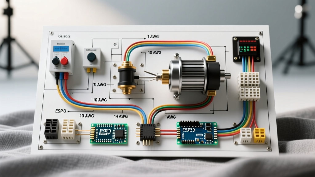
Below is the logical flow for a properly protected, panel-integrated winch wiring diagram. This setup separates the high-current motive path from the low-current control path.
1. The High-Current Motive Path
- Battery Positive Terminal: Connect a 2/0 AWG (for 10k+ lb winches) or 2 AWG (for 8k lb winches) tinned marine copper cable.
- Main Breaker Integration: Route the positive cable into the primary DC distribution busbar or directly into the Line terminal of your heavy-duty panel-mount breaker. Mount the breaker within 7 inches of the battery positive post to protect the entire feed cable.
- Contactor Line In: Run the load side of the breaker to Terminal 1 (Line In) of the main winch contactor.
- Winch Motor Feed: Connect Terminal 2 (Load Out) of the contactor directly to the winch motor positive terminal.
- Ground Path: Run a matching gauge negative cable from the battery negative terminal to the winch motor negative terminal. Do not rely on the vehicle chassis for the main winch ground; voltage drop across chassis joints will destroy winch efficiency.
2. The Low-Current Control Path
- Tap a 12V ignition-switched source from your auxiliary fuse panel.
- Run 12 AWG wire through a 10A blade fuse to the winch 'In/Out' rocker switch.
- From the rocker switch, run 14 AWG trigger wires to the small spade terminals on the main contactor coil.
- Ground the contactor coil to the local auxiliary busbar.
Wire Gauge and Breaker Sizing Matrix
Sizing your breaker and wire correctly requires understanding the difference between continuous load and peak stall load. According to Warn Industries installation guidelines, wire must be sized for the maximum expected run time and peak amperage to prevent insulation melt-down. Use 100% copper, stranded, tinned marine wire (UL 1426 or SAE J1128).
| Winch Capacity | Peak Stall Amps | Min. Wire Gauge (AWG) | Breaker Size (Amps) | Recommended Breaker Type |
|---|---|---|---|---|
| 3,000 - 4,500 lbs | 150A - 200A | 6 AWG | 150A | Surface Mount Thermal |
| 8,000 - 10,000 lbs | 350A - 430A | 2 AWG or 1/0 AWG | 300A | Panel Mount Magnetic/Thermal |
| 12,000 - 16,500 lbs | 450A - 600A+ | 2/0 AWG | 500A | Class T Fuse or MEGA Fuse |
Expert Insight: Never size your breaker to the peak stall amperage. Size it to the maximum continuous safe carrying capacity of your wire. The breaker's job is to protect the wire from catching fire during a prolonged stall, not to protect the winch motor from burning out. If you stall a winch for more than 60 seconds, the motor will overheat regardless of the breaker size.
Panel Integration and Hardware Specifics
Integrating a winch circuit into a custom DC panel requires strict adherence to torque specifications and environmental sealing. In off-road and marine environments, vibration and moisture are the primary enemies of high-amperage connections.
Lug Crimping and Sealing
Do not use cheap stamped-copper lugs. Invest in heavy-wall, tinned copper lugs (e.g., Ancor or Quick Cable). After crimping with a hydraulic or hex-indent crimper, seal the barrel with 3M FP-301 adhesive-lined heat shrink. The adhesive melts and fills the voids between the wire strands, preventing capillary action from drawing moisture into the copper.
Torque Specifications
High-amperage connections loosen over time due to thermal cycling (expansion and contraction). Under-torqued lugs create high resistance, leading to localized heating and voltage drop. Use a calibrated inch-pound torque wrench for all busbar and breaker terminations:
- 6 AWG Lugs (1/4" stud): 60 to 75 in-lbs
- 2 AWG Lugs (5/16" stud): 110 to 130 in-lbs
- 2/0 AWG Lugs (3/8" stud): 180 to 220 in-lbs
The Impact of Battery Chemistry on Winch Wiring
As we move further into 2026, the shift from AGM/Lead-Acid to Lithium Iron Phosphate (LiFePO4) batteries drastically changes how a winch panel behaves. Battery University notes that lithium cells maintain a much higher resting voltage under heavy load compared to lead-acid.
While this is great for winch speed, it means your contactor and wiring will sustain higher continuous amperage for longer periods before the battery voltage sags to the point where the winch slows down. If you are upgrading to a high-output lithium cranking battery (like a RELiON or Dakota Lithium), you must upgrade your winch wiring from 2 AWG to 1/0 AWG, even on an 8,000 lb winch, to handle the sustained thermal load without exceeding a 3% voltage drop across the circuit.
Troubleshooting Common Panel and Breaker Failures
Even with a perfect wiring diagram for a winch, field failures occur. Here is how to diagnose the most common panel-level issues:
1. Nuisance Tripping Under Moderate Load
Symptom: The main breaker trips when winching a load that is only 50% of the winch's rated capacity.
Cause: You are likely using a purely thermal breaker mounted in a hot engine bay. Thermal breakers trip based on ambient heat plus electrical heat.
Fix: Relocate the breaker to a cooler area, or swap to a magnetic-hydraulic breaker (like the Blue Sea 285-Series) which trips strictly on current flow, ignoring ambient engine bay temperatures.
2. Contactor Chatter (Rapid Clicking)
Symptom: The winch contactor clicks rapidly without engaging the motor, or drops out intermittently.
Cause: Severe voltage drop in the control circuit or the main ground path. If the voltage at the contactor coil drops below 9.5V under load, the magnetic field collapses, opening the contactor, which restores voltage, closing it again in an endless loop.
Fix: Check the ground path of the control circuit. Ensure the rocker switch and control wiring are drawing from a clean, dedicated busbar rather than a shared, high-resistance chassis ground.
3. Melted Lug Insulation
Symptom: The heat shrink or insulation near the battery terminal or breaker stud is melted or discolored.
Cause: Improper crimping or under-torqued hardware creating a high-resistance joint.
Fix: Cut off the damaged lug. Inspect the wire for copper oxidation (green/black discoloration). If oxidized, cut back to clean copper, install a new heavy-wall lug, crimp properly, and torque to spec.