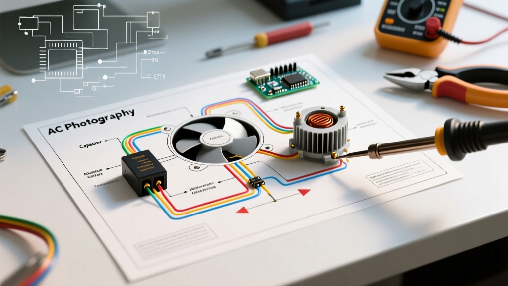

Mastering the Wiring Diagram for AC Fan Motor Troubleshooting
In modern HVAC diagnostics, guessing is not an option. Whether you are servicing a legacy 14-SEER system or a 2026-compliant high-efficiency heat pump, the wiring diagram for AC fan motor circuits is your primary roadmap. A fan motor that fails to start, hums without rotating, or trips the breaker requires a systematic approach rooted in schematic literacy. This guide breaks down how to trace circuits, test components, and isolate faults in both Permanent Split Capacitor (PSC) and Electronically Commutated Motor (ECM) systems using manufacturer wiring diagrams.
Decoding the Standard PSC Fan Motor Schematic
Despite the industry's shift toward variable-speed technologies, millions of PSC condenser fan motors and indoor blower motors remain in active service. The wiring diagram for a standard PSC motor typically features a 3-speed or 4-speed configuration. Understanding the color-coded schematic is the first step in effective troubleshooting.
Standard PSC Wire Color Codes and Diagram Tracing
- Black (High Speed): Connects to the highest RPM tap, usually routed through the compressor contactor or fan relay.
- Blue (Medium Speed) & Red (Low Speed): Used for multi-stage cooling or continuous fan circulation modes.
- White (Common): The return path to the 240V/120V power source.
- Brown & Brown/White (Capacitor Leads): These connect exclusively to the run capacitor and do not route back to the main power or contactor.
Expert Insight: A common mistake among junior technicians is swapping the Brown and Brown/White leads or tying one to neutral. The wiring diagram explicitly shows these leads bridging the start and auxiliary windings through the capacitor. Reversing them won't change rotation, but miswiring them to a power source will instantly destroy the start winding.
Step-by-Step PSC Troubleshooting Using the Diagram
When the condenser fan motor fails to engage, use the wiring diagram to isolate the failure to either the power supply, the run capacitor, or the motor windings. Always verify power is disconnected via a lockout/tagout (LOTO) procedure before touching terminals.
Step 1: Capacitor Testing (The Most Common Culprit)
Locate the dual run capacitor on the schematic. A standard 3-ton residential unit typically utilizes a 45/5 MFD (Microfarad) or 50/5 MFD capacitor rated at 370VAC or 440VAC. The fan side is the 5 MFD terminal.
- Set your digital multimeter to the capacitance setting (µF).
- Discharge the capacitor using a 20,000-ohm, 5-watt resistor across the C (Common) and FAN terminals.
- Measure across C and FAN. A reading of 4.7 µF to 5.3 µF is acceptable (industry standard allows a +/- 6% variance).
- If the reading drops below 4.5 µF, the capacitor is weak, causing the motor to draw high amperage and trip the internal thermal overload.
Step 2: Motor Winding Continuity (The R + S = C Rule)
If the capacitor tests perfectly, the wiring diagram directs you to the motor's internal windings. Disconnect all motor leads and set your multimeter to the lowest Ohms setting (Rx1 or 200Ω).
- Common to Run (White to Black): Expect a low resistance reading (e.g., 2 to 4 ohms).
- Common to Start (White to Brown): Expect a higher resistance reading (e.g., 5 to 8 ohms).
- Run to Start (Black to Brown): This must equal the sum of the previous two readings.
The Golden Rule of Motor Diagnostics: If your Run-to-Start reading does not exactly equal Common-to-Run plus Common-to-Start, you have an internal short between the windings. The motor is internally compromised and must be replaced, regardless of what the exterior of the wiring diagram suggests.
The 2026 Landscape: Troubleshooting ECM Fan Motors
As of 2026, Department of Energy (DOE) efficiency mandates have made Electronically Commutated Motors (ECMs) the standard for new indoor air handlers and high-end condenser units. The wiring diagram for an ECM fan motor looks radically different from a PSC schematic. Instead of line-voltage speed taps, you will see a 3-pin high-voltage power connector and a 5-pin low-voltage control connector.
Tracing the ECM 5-Pin Control Harness
When an ECM blower fails, the wiring diagram shifts your focus from the motor itself to the control board and the thermistor. The 5-pin connector typically carries:
- 120VAC / 240VAC (Pin 1): Constant line voltage for the motor's internal inverter.
- 24VAC (Pin 2): Control voltage from the thermostat or main board.
- Common (Pin 3): 24V return path.
- Comfort / Profile (Pin 4): Signals the motor to adjust torque based on cooling vs. heating profiles.
- Thermistor (Pin 5): A temperature sensor that prevents the motor from overheating.
Troubleshooting Tip: If the wiring diagram shows 24VAC present at Pins 2 and 3, but the motor remains dead, check the thermistor circuit. A faulty thermistor will signal the internal module to lock out the motor to prevent a fire hazard.
Diagnostic Matrix: Symptom to Schematic Tracing
Use this quick-reference table to map physical symptoms directly to tracing points on your AC fan motor wiring diagram.
| Observed Symptom | Diagram Trace Point | Likely Culprit | Corrective Action |
|---|---|---|---|
| Motor hums, won't start, pushes easily by hand | Capacitor (C to FAN) | Open Run Capacitor | Replace with exact MFD/Voltage rating |
| Motor runs for 5 mins, then shuts off until cool | Motor Internal Overload / Amp Draw | Failing Bearings / Weak Capacitor | Check amp draw vs. FLA on nameplate; replace motor if bearings are binding |
| Condenser fan runs backward | Contactor to Motor (L1/L2) | Incorrect Phase / Aftermarket Motor Wiring | Swap L1 and L2 line voltage feeds at the contactor |
| ECM Blower surges or pulses air | 5-Pin Harness (Thermistor Pin) | Failing Thermistor / Control Board Relay | Test thermistor resistance (usually 10kΩ at 75°F); replace harness or module |
| Breaker trips instantly upon contactor pull-in | Compressor & Fan Common Feed | Shorted Fan Winding to Ground | Megger test motor windings to ground; replace shorted motor |
Safety, Code Compliance, and Authoritative Standards
Troubleshooting live 240V circuits requires strict adherence to electrical codes. According to the NFPA 70 (National Electrical Code), all outdoor HVAC equipment must have a clearly marked, readily accessible disconnect switch within sight of the unit. Never rely solely on the thermostat or the main breaker panel to isolate power while tracing a wiring diagram.
Furthermore, when replacing components identified via your schematic troubleshooting, always match the original equipment manufacturer (OEM) specifications. The U.S. Department of Energy emphasizes that improper replacement of fan motors or capacitors can drastically reduce the SEER rating of the system, leading to increased energy consumption and premature compressor failure due to inadequate head pressure management.
Final Thoughts on Schematic Literacy
A wiring diagram for an AC fan motor is not just a picture of where wires go; it is a logical flowchart of electrical potential. By mastering the ability to read line-voltage paths, isolate control-voltage signals, and apply the mathematical rules of motor windings, you transition from a parts-swapper to a true diagnostic technician. Always keep a digital copy of the unit's schematic on your phone, verify your multimeter's calibration annually, and trust the diagram over your assumptions.