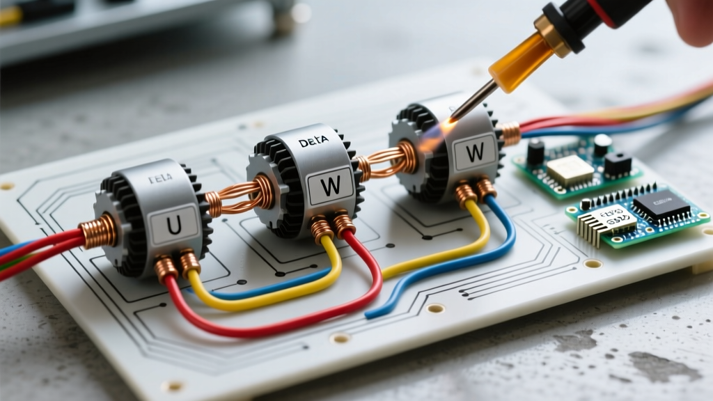

Introduction to 3-Phase Motor Configurations
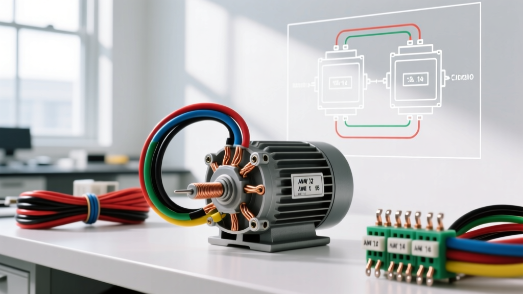
When tackling electric motor wiring 3 phase installations, understanding the internal winding topology is just as critical as selecting the correct wire gauge. Most industrial and heavy-commercial 3-phase induction motors (such as the WEG W22 or Baldor-Reliance M3558T series) are dual-voltage, 9-lead machines. This design allows the same motor to operate on either 230V (low voltage) or 460V (high voltage) 3-phase systems by reconfiguring the internal stator windings into either a Wye (Star) or Delta topology.
This comprehensive walkthrough details the exact steps for wiring a 9-lead NEMA-standard motor, ensuring compliance with the National Electrical Code (NEC) and preventing catastrophic winding failures caused by misconfiguration.
CRITICAL SAFETY WARNING: Never assume a circuit is de-energized. Always perform Lockout/Tagout (LOTO) procedures and verify zero energy using a Category IV multimeter, such as the Fluke 87V, before touching any motor terminals. Reference NFPA 70 (NEC) Article 430 for mandatory motor circuit safety standards.
Pre-Wiring Preparation & Lead Identification
Before making any terminations, you must identify the motor lead standard. In North America, NEMA standard MG-1 dictates that 9-lead motors use T1 through T9 designations. (Note: IEC standard motors use U1, V1, W1, etc., which require a different mapping). For this guide, we are strictly following the NEMA T1-T9 nomenclature.
Verifying the Nameplate Data
- Voltage Rating: Confirm if the application requires 230V or 460V.
- Connection Diagram: Locate the wiring schematic on the motor's inner peckerhead cover. It will explicitly show the Wye and Delta grouping for both high and low voltages.
- Full Load Amps (FLA): Note the FLA for your selected voltage to calculate breaker and wire sizing later.
Step-by-Step Walkthrough: Low Voltage Wye (Star) Connection
The Wye (or Star) configuration is frequently used for low-voltage (230V) applications where a smoother startup and lower starting current are desired. In a Wye setup, the windings are connected to a common neutral point, and the line voltage is applied across two series-connected windings.
Step 1: Isolate and Group the Neutral Leads
- Locate leads T4, T5, and T6.
- Strip 3/4 inch of insulation from each lead (assuming 10 AWG THHN wire).
- Join T4, T5, and T6 together using a properly sized closed-end crimp connector or a wire nut rated for the combined gauge and vibration environment.
- Insulate the connection thoroughly with high-quality electrical tape or heat shrink. This joint will not be connected to any line power.
Step 2: Apply Line Power to the Phase Legs
- Connect Phase Line 1 (L1) to both T1 and T7.
- Connect Phase Line 2 (L2) to both T2 and T8.
- Connect Phase Line 3 (L3) to both T3 and T9.
Pro-Tip: Use parallel terminal lugs or dual-hole mechanical lugs to secure two wires under a single terminal screw if your motor terminal block does not have dedicated bus bars for parallel connections.
Step-by-Step Walkthrough: Low Voltage Delta Connection
Delta wiring is the standard for low-voltage (230V) applications requiring maximum starting torque, such as conveyor belts, rock crushers, and heavy compressors. In a Delta setup, the windings are connected end-to-end in a triangular loop, and line voltage is applied directly across each individual winding.
Step 1: Create the Delta Loops
Instead of a common neutral, you will create three distinct junction points where the line power will land.
- Junction 1: Group leads T1, T6, and T7 together.
- Junction 2: Group leads T2, T4, and T8 together.
- Junction 3: Group leads T3, T5, and T9 together.
Step 2: Connect the Phases
- Connect Phase Line 1 (L1) to Junction 1 (T1, T6, T7).
- Connect Phase Line 2 (L2) to Junction 2 (T2, T4, T8).
- Connect Phase Line 3 (L3) to Junction 3 (T3, T5, T9).
3-Phase Motor Wiring Comparison Matrix
Choosing between Wye and Delta for low-voltage applications depends entirely on the mechanical load characteristics. Refer to the matrix below to make an informed engineering decision.
| Characteristic | Wye (Star) Configuration | Delta Configuration |
|---|---|---|
| Starting Torque | Low (Approx. 33% of Delta) | High (100% Rated Torque) |
| Starting Current (Inrush) | Low (Reduces voltage dip) | High (Can cause grid sag) |
| Ideal Applications | Centrifugal pumps, fans, blowers | Conveyors, compressors, hoists |
| Voltage per Winding (230V Sys) | 132V (Line / √3) | 230V (Full Line Voltage) |
Wire Sizing, Breaker Selection, and Torque Specifications
Proper electric motor wiring 3 phase setups require strict adherence to NEC sizing rules. Let's use a practical example: a 10 HP, 460V, 3-phase motor.
1. Calculating Wire Gauge
According to NEC Table 430.250, a 10 HP motor at 460V has a Full Load Amp (FLA) rating of 14A. NEC Article 430.22 requires motor branch circuit conductors to be sized at 125% of the FLA.
- 14A × 1.25 = 17.5 Amps.
- Based on NEC Table 310.16 (90°C column for THHN), 12 AWG copper wire (rated 30A at 90°C, 25A at 75°C) is the minimum acceptable size. However, if the run exceeds 50 feet, upgrade to 10 AWG to mitigate voltage drop below the recommended 3% threshold.
2. Sizing the Overcurrent Protection
For an inverse-time circuit breaker, NEC Table 430.52 allows sizing up to 250% of the FLA for standard 3-phase motors.
- 14A × 2.50 = 35A. Since 35A is not a standard breaker size, you may round up to the next standard size, which is 40 Amps.
3. Terminal Torque Specifications
Under-torqued connections cause high-resistance joints, leading to localized heating and eventual single-phasing failures. Over-torquing strips the brass terminal threads. Always use a calibrated torque screwdriver (e.g., CDI 401SM).
- 14 AWG to 10 AWG terminals: 35 to 45 in-lbs.
- 8 AWG to 4 AWG terminals: 50 to 75 in-lbs.
- 2 AWG to 1/0 AWG terminals: 100 to 120 in-lbs (consult manufacturer peckerhead data for exact values).
Troubleshooting Common 3-Phase Wiring Faults
Even with a meticulous walkthrough, field conditions can introduce errors. Here is how to diagnose the most common 3-phase wiring faults post-installation.
Fault 1: Incorrect Phase Rotation (Motor Runs Backward)
Symptom: A centrifugal pump cavitates, or a fan pushes air backward immediately upon startup.
Cause: The sequence of L1, L2, and L3 does not match the motor's internal winding orientation.
Fix: De-energize the circuit, swap any two of the three line power leads (e.g., swap L1 and L2), and re-test. For critical systems, verify rotation before coupling the load using an Amprobe PRM-6 phase rotation meter or by performing a 'bump' test.
Fault 2: Single-Phasing
Symptom: The motor hums loudly, fails to start, or trips the overload relay within seconds. If running, it will overheat rapidly and draw unbalanced current.
Cause: One of the three phases is lost due to a blown fuse, a failed contactor pole, or a broken wire.
Fix: Measure phase-to-phase voltage at the motor terminal block while the contactor is engaged. You should read ~230V or ~460V across L1-L2, L2-L3, and L1-L3. Any reading significantly lower or at 0V indicates an open circuit upstream.
Fault 3: Winding Burnout from Topology Mismatch
Symptom: Immediate tripping of the main breaker, accompanied by a burning insulation smell and smoke from the peckerhead.
Cause: The motor was wired in Delta for a 460V high-voltage supply, but the nameplate required a Wye connection. In a high-voltage Wye setup, each winding sees 265V. If wired in Delta on a 460V system, each winding receives the full 460V—nearly double its rated voltage—causing instantaneous magnetic saturation and thermal destruction.
Fix: The motor must be rewound or replaced. Always triple-check the nameplate schematic against the physical wire grouping before applying power.
Authoritative References & Standards
For continuous learning and code compliance, refer to the following industry standards governing 3-phase motor installations:
- National Fire Protection Association (NFPA): NEC Article 430 - Covers motors, motor circuits, and controllers.
- National Electrical Manufacturers Association (NEMA): MG-1 Standard - Defines motor lead markings, tolerances, and terminal dimensions.
- Fluke Corporation: Motor Troubleshooting Guide - Practical field diagnostics for 3-phase electrical systems.