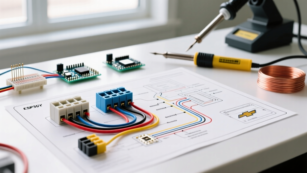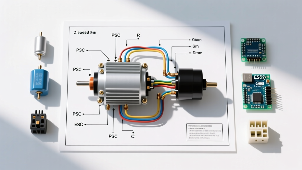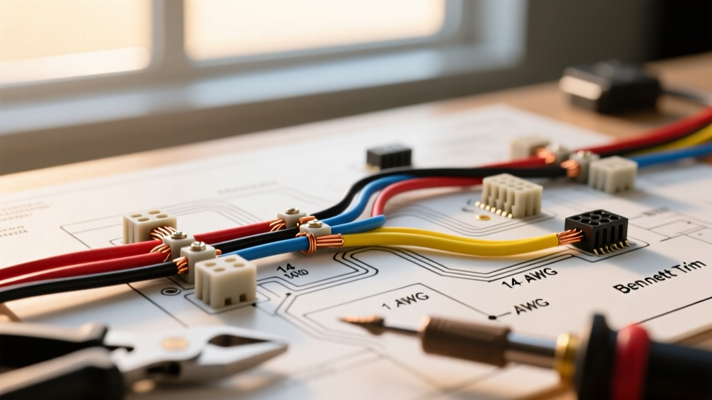

Mastering the Wiring Diagram for Bennett Trim Tabs
Installing or troubleshooting marine trim tabs requires strict adherence to electrical standards. When working with the industry-standard wiring diagram for Bennett trim tabs, understanding the precise color codes and wire gauge requirements is the difference between a reliable system and a frustrating failure on the water. As of 2026, marine electrical best practices heavily emphasize ABYC E-11 compliance, voltage drop mitigation, and the exclusive use of marine-grade tinned copper wire.
Bennett Marine produces two primary categories of trim tabs: Hydraulic systems (like the classic V351HPU and M8000 series) and Electric systems (like the Bolt and EdgeMax linear actuators). The wiring diagrams for these two architectures differ drastically in current draw, wire gauge requirements, and harness color mapping. This comprehensive reference guide breaks down the exact specifications you need for a flawless installation.
Bennett Trim Tab Wire Color Code Matrix
Bennett utilizes a standardized color-coded harness system across its helm controls and pump/actuator assemblies. Swapping these wires is the most common cause of inverted tab movement (e.g., pressing 'Port Bow Down' raises the starboard tab). Below is the definitive color code reference for standard Bennett hydraulic and electric setups.
| Wire Color | Hydraulic Function (V351 / M8000) | Electric Function (Bolt / EdgeMax) | Standard Harness Gauge |
|---|---|---|---|
| Red | 12V DC Positive to Hydraulic Pump Motor | 12V DC Positive to Actuator Relay | 10 AWG |
| Black | System Ground (Pump & Valves) | System Ground (Actuators) | 10 AWG |
| White | Port Bow Down (Solenoid Valve) | Port Bow Down (Actuator Motor) | 16 AWG / 12 AWG |
| Blue | Port Bow Up (Solenoid Valve) | Port Bow Up (Actuator Motor) | 16 AWG / 12 AWG |
| Yellow | Starboard Bow Down (Solenoid Valve) | Starboard Bow Down (Actuator Motor) | 16 AWG / 12 AWG |
| Green | Starboard Bow Up (Solenoid Valve) | Starboard Bow Up (Actuator Motor) | 16 AWG / 12 AWG |
| Orange | Indicator Light Power (LED Rocker Switch) | Sensor / Auto-Tab Feedback Signal | 18 AWG |
Expert Note on Grounding: Never rely on the engine block or a shared ground bus for trim tab systems. Bennett explicitly requires the Black ground wire to be routed directly back to the vessel's main negative bus bar or the battery's negative terminal to prevent stray current corrosion and solenoid chatter.
Wire Gauge Selection & Voltage Drop Calculations
Selecting the correct wire gauge is critical. Marine environments are hostile, and undersized wires lead to voltage drop. For trim tab motors, a voltage drop exceeding 5% will result in sluggish deployment, overheated actuators, and rapid clicking of the hydraulic solenoid valves due to insufficient voltage to hold the magnetic field.
Hydraulic Systems (V351HPU)
The hydraulic pump motor typically draws between 8 to 12 amps under load. However, the solenoid valves that direct the hydraulic fluid only draw about 1 amp each.
- Main Power (Red/Black): Use 10 AWG marine-grade tinned copper for runs up to 15 feet. If the distance from the battery to the transom-mounted pump exceeds 15 feet, step up to 8 AWG to maintain a 3% voltage drop.
- Control Wires (White, Blue, Yellow, Green): The factory Bennett harness uses 16 AWG for these valve wires. Because the amperage is so low (~1A), 16 AWG is perfectly adequate for runs up to 20 feet. If you are splicing or extending, use 14 AWG minimum for mechanical durability.
Electric Systems (Bolt & EdgeMax)
Electric trim tabs eliminate the hydraulic pump and fluid lines, relying instead on 12V DC linear actuators mounted directly on the transom. These actuators draw significantly more current—often 12 to 15 amps per actuator under heavy load.
- Main Power & Actuator Leads: You must use a minimum of 10 AWG for all power and control wires (Red, Black, White, Blue, Yellow, Green) extending to the actuators. For vessels over 25 feet where wire runs exceed 18 feet, 8 AWG is mandatory to prevent the internal thermal breakers in the actuators from tripping during operation.
For precise calculations based on your specific vessel's dimensions, consult the West Marine Wire Size and Ampacity Guide to ensure your custom runs meet the 3% voltage drop threshold recommended for non-critical motor loads.
Overcurrent Protection & ABYC Compliance
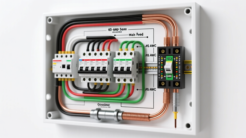
According to ABYC E-11 standards governing AC and DC electrical systems on boats, overcurrent protection must be installed within 7 inches of the power source connection. If this is not physically possible, the wire must be enclosed in a continuous protective sheath (like a split loom or conduit) up to the breaker.
Breaker Sizing Reference
- V351HPU (Standard Hydraulic): 20-Amp manual reset circuit breaker.
- M8000 / M12000 (High-Flow Hydraulic): 30-Amp manual reset circuit breaker.
- Bolt Electric Actuators (Pair): 30-Amp or 40-Amp manual reset breaker, depending on the combined stall current of the specific actuator model.
Always use marine-rated, ignition-protected (SAE J1171) circuit breakers if the breaker is mounted in the engine compartment where fuel vapors may be present.
Step-by-Step Routing and Connection Best Practices
- Plan the Route: Run the Bennett harness through the rigging tube or a dedicated conduit. Keep DC power wires at least 12 inches away from NMEA 2000 backbones or VHF antenna coax to prevent electromagnetic interference (EMI).
- Use Heat-Shrink Terminals: Never use standard vinyl or nylon crimp terminals. Use adhesive-lined, marine-grade heat-shrink terminals (e.g., Ancor or 3M) to create a waterproof seal that prevents capillary action from drawing moisture into the copper strands.
- Apply Dielectric Grease: Before mating the Deutsch-style or Molex connectors at the helm switch and the transom actuators, apply a liberal amount of marine dielectric grease to the pins to prevent galvanic corrosion.
- Secure the Harness: Use UV-resistant cable ties every 18 inches. Ensure the wire has a 'service loop' (a slight drip loop) before entering the transom hole to prevent water from tracking down the wire into the hull.
Troubleshooting Common Wiring Faults
Even with a perfect wiring diagram for Bennett trim tabs in hand, marine environments introduce variables that cause failures. Here is how to diagnose the most frequent issues:
Symptom: Solenoid Clicks Rapidly, But Tabs Do Not Move
The Cause: Severe voltage drop on the Red (power) or Black (ground) wire. The solenoid engages, but the voltage drops below the holding threshold when the pump motor draws current, causing the solenoid to disengage and re-engage rapidly.
The Fix: Use a digital multimeter to measure voltage directly at the pump terminals while the switch is depressed. If it reads below 10.5V, inspect the main breaker for corrosion, upgrade the wire gauge, or clean the main battery bus connections.
Symptom: Tabs Move in the Opposite Direction of the Switch
The Cause: Swapped control wires at the helm or the transom junction.
The Fix: Verify the color mapping. If pressing 'Port Bow Down' raises the Starboard tab, the White (Port Down) and Yellow (Starboard Down) wires are likely reversed. Swap them at the helm rocker switch terminal block.
Symptom: One Tab Deploys Slower Than the Other
The Cause: High resistance in the specific control wire (White, Blue, Yellow, or Green) or a failing solenoid valve coil.
The Fix: Disconnect the suspect wire at the helm and the pump. Perform a continuity and resistance test. A healthy 16 AWG wire run should show near-zero resistance (under 0.5 ohms). If resistance is high, the wire is internally corroded and must be replaced.
Frequently Asked Questions (FAQ)
Can I use automotive wire instead of marine-grade tinned copper?
While automotive wire will conduct electricity, it is strictly against ABYC guidelines and highly discouraged. Automotive wire features untinned copper that rapidly oxidizes (turns black/green) in saltwater environments, leading to 'black wire disease' where corrosion wicks inside the insulation and destroys the entire harness. Always use UL 1426 marine-grade tinned wire.
Do I need to wire the Bennett LED indicator lights to a separate switch?
No. The Orange wire on modern Bennett LED rocker switches is designed to receive 12V positive from your vessel's navigation or running light circuit. This ensures the tab indicator lights only illuminate when you are actively running the boat at night, preventing dashboard glare and preserving night vision.
Where can I find the official schematic for my specific serial number?
Bennett Marine frequently updates its harness designs. You can download the exact PDF schematic for your system by visiting the Bennett Marine Support Portal and entering your pump or actuator serial number.
Final Thoughts on Marine Electrical Safety
Properly executing the wiring diagram for Bennett trim tabs ensures your vessel planes faster, burns less fuel, and handles rough chop with stability. By respecting wire gauge limits, adhering to the precise color code matrix, and utilizing marine-grade overcurrent protection, you guarantee a system that will perform reliably for years to come. Always prioritize connection integrity and route your harnesses with future maintenance in mind.