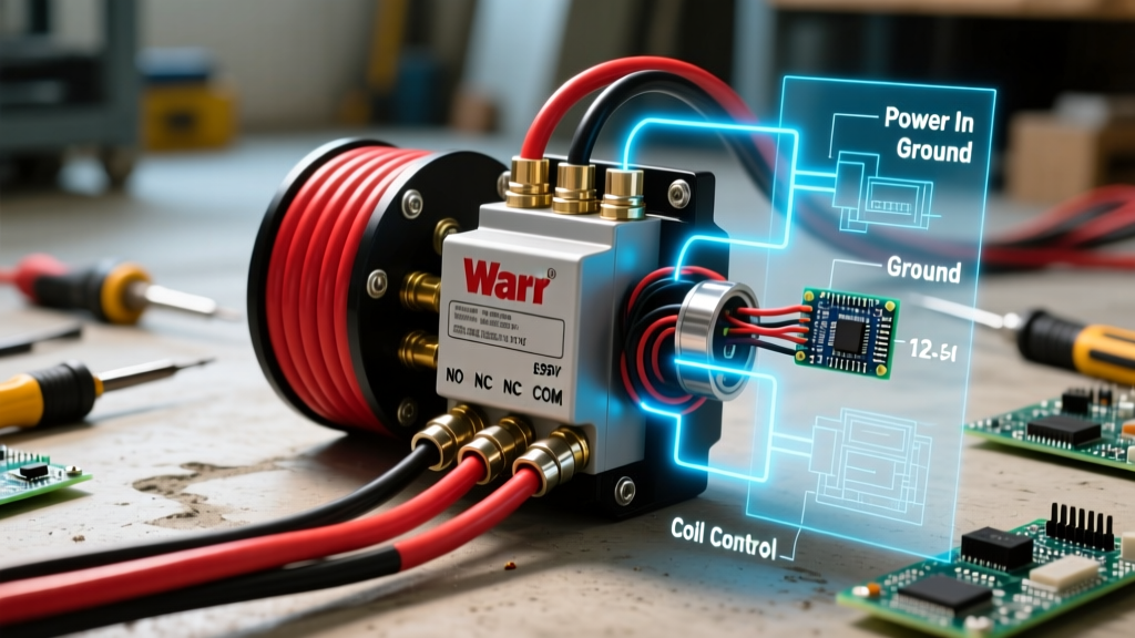

Understanding the Wiring Diagram for Warn Winch Systems
When installing a heavy-duty recovery system on your truck or Jeep, referencing a correct and comprehensive wiring diagram for Warn winch applications is critical for both performance and safety. Warn Industries remains the gold standard in off-road recovery, with popular 2026 models like the VRX 10-S (retailing around $699) and the premium Zeon 10-S (approximately $1,299) demanding robust electrical architectures. A winch motor under maximum load can draw upwards of 400 amps. If your wiring harness, contactor, or circuit protection is undersized, you risk severe voltage drop, melted insulation, or catastrophic electrical fires.
This guide breaks down the exact electrical topology required for traditional 12V DC Warn winches, explains the control circuit logic, and contrasts older 4-terminal solenoid setups with the integrated digital contactors found in the newer Warn Axon series.
Core Components of the Warn Winch Circuit
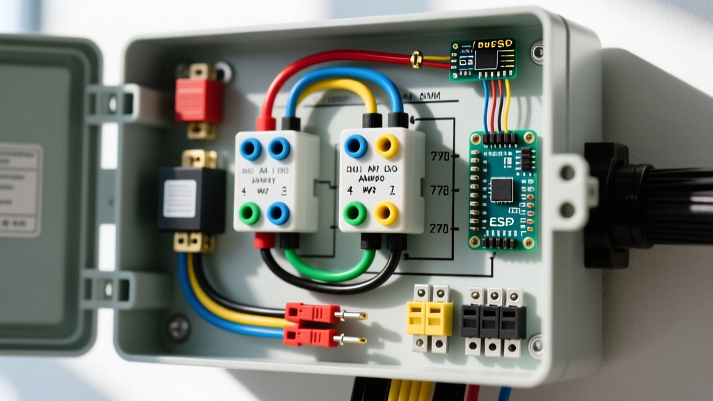
Before tracing the wiring paths, you must identify the primary nodes in the circuit. A standard Warn winch installation relies on four main electrical components:
- The Motor: Typically a series-wound DC motor (in heavy-duty models like the Zeon) or a permanent magnet motor (in lighter duty models). Series-wound motors draw massive current but offer superior line-pull consistency.
- The Contactor (Solenoid Pack): An electrically operated switch capable of handling 400A+ peak loads. Warn utilizes Albright-style industrial contactors (Part #72631) in many of their premium setups, which are vastly superior to standard 4-post automotive starter solenoids.
- Circuit Breaker: A marine-grade, surface-mount thermal breaker (typically 150A to 200A) installed between the battery and the contactor to prevent thermal runaway during dead-pull scenarios.
- Control Receptacle: The 5-pin or 3-pin weatherproof connector mounted in the grille, allowing the handheld pendant or wireless receiver to trigger the contactor coils.
Step-by-Step Main Power Routing
The main power circuit carries the high-amperage load from the vehicle's battery to the winch motor. According to SAE J1128 standards for low-tension primary automotive cable, you must use high-strand-count, pure copper wire. Avoid Copper-Clad Aluminum (CCA) wire, which suffers from higher resistance and brittle termination points.
1. Battery to Circuit Breaker
Run a 2 AWG or 1/0 AWG marine-tinned copper cable from the positive battery terminal to the input stud of a 200A circuit breaker (such as the Blue Sea Systems 7182). Keep this run as short as possible. Torque the terminal nuts to 12-15 Nm to prevent micro-arcing.
2. Circuit Breaker to Contactor (Post A)
From the output side of the breaker, run the same gauge wire to the primary input stud on the contactor (often labeled 'A' or 'BAT'). This stud remains 'hot' whenever the breaker is closed.
3. Contactor to Winch Motor (Post B)
Connect the secondary high-current stud on the contactor (labeled 'B' or 'MOT') directly to the positive terminal on the Warn winch motor housing. Ensure the routing avoids exhaust manifolds and steering linkages.
4. Ground Return Path
Run a dedicated 2 AWG ground cable from the winch motor's negative terminal directly to the negative battery terminal or a verified, bare-metal chassis ground point with a minimum 1/2-inch bolt penetration. Do not rely on the winch mounting plate for the primary ground return; paint and powder coating will cause massive resistance.
Control Circuit Wiring: Triggering the Contactor
The control circuit uses low-amperage 14 AWG or 16 AWG wire to energize the contactor's electromagnetic coils. Warn's standard 5-pin remote receptacle follows a specific pinout logic:
| Pin | Function | Wire Color (Typical) | Destination |
|---|---|---|---|
| 1 | 12V+ Power In | Red (14 AWG) | Fused ignition source or direct battery (via inline 10A fuse) |
| 2 | Spool In (Power In) | Yellow (16 AWG) | Contactor Coil Terminal 'IN' |
| 3 | Spool Out (Power Out) | Green (16 AWG) | Contactor Coil Terminal 'OUT' |
| 4 | Ground | Black (14 AWG) | Chassis Ground / Battery Negative |
| 5 | Accessory / LED Indicator | White (18 AWG) | Dashboard LED or Accessory Relay |
When you press 'IN' on the remote, 12V flows through Pin 2, energizing the first coil inside the contactor. This creates a magnetic field that pulls the heavy-duty copper disc down, bridging Post A and Post B, and sending 400A to the winch motor.
Contactor Configurations: 3-Terminal vs. 4-Terminal
Depending on the exact Warn model and year, you will encounter either a 3-terminal (grounded coil) or 4-terminal (isolated coil) contactor. Miswiring these is the most common cause of dead winches.
4-Terminal (Isolated Coil) Setup
Common in older M8000 and M12000 models. The contactor has two large power studs and two small coil studs. The small studs require a dedicated 12V+ trigger and a dedicated ground. The coil circuit is completely isolated from the main power path.
3-Terminal (Grounded Coil) Setup
Standard on many VRX and Zeon configurations. The contactor has two large power studs and only one small trigger stud. The internal coil is grounded through the contactor's metal mounting bracket. Crucial Note: If you mount a 3-terminal contactor on a painted surface or use rubber isolation bushings without providing a dedicated ground jumper wire to the bracket, the winch will not engage.
Wire Gauge Selection and Voltage Drop
Sizing your wire correctly is governed by the distance of the run and the peak amperage. The NFPA 70 (National Electrical Code) provides baseline ampacities, but automotive 12V systems require stricter voltage drop limits (ideally under 3% or 0.36V) to maintain winch torque.
| Wire Gauge (AWG) | Max Run Length (One Way) | Peak Amp Capacity (Automotive) | Voltage Drop at 400A |
|---|---|---|---|
| 4 AWG | Under 5 feet | 160A Continuous | ~0.50V (Marginal) |
| 2 AWG | 5 to 12 feet | 210A Continuous | ~0.32V (Acceptable) |
| 1/0 AWG | 12 to 18 feet | 260A Continuous | ~0.20V (Optimal) |
| 2/0 AWG | Over 18 feet | 300A Continuous | ~0.16V (Best for Rear Mounts) |
Note: If you are mounting a winch in the rear of a long-bed truck or a full-size SUV, you must upgrade to 1/0 AWG or 2/0 AWG to compensate for the extended cable run from the front-mounted battery.
The 2026 Paradigm Shift: Warn Axon Integrated Digital Contactors
If you are installing a modern Warn Axon series winch, the traditional wiring diagram for Warn winch setups no longer applies. The Axon 4500 and Axon 5500 models feature a revolutionary solid-state digital contactor integrated directly into the motor housing. This eliminates the external Albright contactor, the messy control wires, and the 5-pin grille receptacle.
For the Axon series, the wiring diagram is reduced to:
- 1/0 AWG Positive from Battery to Circuit Breaker to Winch Motor Positive Stud.
- 1/0 AWG Negative from Winch Motor Negative Stud to Battery Ground.
- A single, sealed digital communication cable routed to the cab for the wireless display module.
This integrated design reduces voltage drop, eliminates external contactor failure points, and provides real-time amperage and temperature monitoring via Bluetooth.
Common Failure Modes and Troubleshooting
Expert Warning: Never bypass a welded contactor by jumping the main power studs with a screwdriver. The resulting 400A arc flash can cause severe burns and instantly vaporize the metal tool.
Failure Mode 1: Contactor Welding
Symptom: The winch continues to spool in one direction even after releasing the remote button.
Cause: High amperage draw over an extended period has melted the internal copper disc, fusing it to the contact posts. This often happens when users exceed the winch's rated line pull without using a snatch block.
Fix: Disconnect the battery immediately. Replace the contactor pack. Install a thermal cutoff switch or upgrade to an Albright DC contactor rated for higher intermittent loads.
Failure Mode 2: Severe Voltage Drop
Symptom: The winch motor clicks, the vehicle headlights dim severely, but the drum does not turn under load.
Cause: Undersized wiring, corroded battery terminals, or relying on the chassis for the ground return.
Fix: Use a multimeter to measure voltage directly at the winch motor studs while under load. If it drops below 10.5V, upgrade to 1/0 AWG wire and install a secondary auxiliary battery dedicated to the winch.
Failure Mode 3: Water Ingress in Control Receptacle
Symptom: The winch activates randomly or blows the 10A inline control fuse.
Cause: The 5-pin grille receptacle cap was left off during a water crossing, causing a short between Pin 1 (12V+) and Pin 2 (Spool In).
Fix: Replace the receptacle. Apply dielectric grease to the pins and always use the threaded weather cap. For extreme environments, hardwire a wireless receiver module inside the engine bay and delete the exterior receptacle entirely.
Final Safety and Torque Specifications
When finalizing your installation, ensure all M8 terminal nuts on the contactor and motor are torqued to 12-15 Nm (8.8-11 lb-ft). Over-torquing can strip the soft brass threads on the motor studs, while under-torquing leads to high-resistance hot spots that will melt the terminal lugs. Finally, wrap all high-current connections in adhesive-lined marine heat shrink and secure the cables with UV-resistant loom every 12 inches to prevent chassis chafing.