
Understanding the Wiring Diagram for a One Wire Alternator
When you first look at a wiring diagram for a one wire alternator, the simplicity can be deceiving. Unlike traditional three-wire setups that require a dedicated ignition excitation wire and a remote voltage sense wire, a one-wire alternator relies on an internal voltage regulator and a self-exciting circuit. This design eliminates the need to run wires through the firewall to the ignition switch, making it a favorite for engine swaps, classic car restomods, and custom off-road builds.
However, simplicity in wiring does not mean you can ignore electrical physics. A poorly executed one-wire installation will result in voltage drop, undercharged batteries, and potentially catastrophic wiring fires. In this comprehensive guide, we will break down the exact wiring schematic, wire gauge requirements, and the hidden edge cases that generic manuals fail to mention.
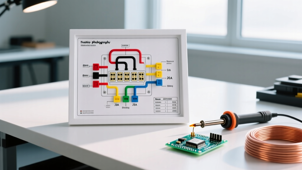
Decoding the Schematic: How the Single Wire Connects
The core of the wiring diagram for a one wire alternator consists of a single heavy-gauge charge wire. Here is the exact path and termination sequence:
- Alternator Output Stud: The charge wire connects directly to the large rear output terminal (usually marked "BAT" or "OUT").
- Overcurrent Protection: A Mega Fuse or ANL fuse is installed inline, within 18 inches of the battery positive terminal.
- Battery Positive Terminal: The wire terminates at the battery positive post or the main positive distribution busbar.
- Grounding: The alternator completes the circuit by grounding through its metal mounting brackets to the engine block. Crucial: You must run a dedicated braided ground strap from the alternator case to the engine block or chassis to ensure a zero-resistance path.
Expert Insight: Never rely solely on the alternator's pivot bracket for grounding. Paint, powder coating, and corrosion will introduce resistance. Always sand the mounting surface to bare metal and use a star washer to bite into the casing.
1-Wire vs. 3-Wire Alternator: A Technical Comparison
Before committing to a one-wire diagram, it is vital to understand the trade-offs. While one-wire setups are cleaner, three-wire setups offer superior voltage regulation in high-draw scenarios.
| Feature | 1-Wire Alternator | 3-Wire Alternator |
|---|---|---|
| Wiring Complexity | Extremely Low (1 main cable) | High (Main cable + IGN + Sense) |
| Voltage Sensing | Local (at the alternator stud) | Remote (at the battery or fuse box) |
| Idle Excitation | Requires engine rev (800-1200 RPM) | Instant (triggered by ignition key) |
| Best Application | Street rods, tractors, simple swaps | High-end audio, winches, LiFePO4 banks |
Step-by-Step Routing and Wire Gauge Selection
Selecting the correct wire gauge is the most common failure point in DIY alternator wiring. According to the SAE J1128 standard for automotive low-tension primary cables, wire ampacity degrades as under-hood temperatures rise. A wire rated for 150 amps at 68°F (20°C) may only safely carry 110 amps at 125°C engine bay temperatures.
Wire Gauge and Fuse Sizing Matrix
Use the following matrix to select your copper wire gauge (stranded, pure copper, not CCA) and corresponding overcurrent protection. These measurements assume a total wire run of up to 15 feet.
| Alternator Max Output | Recommended Wire Gauge | Mega / ANL Fuse Rating |
|---|---|---|
| 80A - 100A | 6 AWG | 125A |
| 120A - 150A | 4 AWG | 175A |
| 180A - 220A | 2 AWG | 250A |
| 240A - 300A+ | 1/0 AWG | 350A |
The Crimping and Termination Process
Do not use solder on high-amperage alternator connections. Solder can melt under high resistance and heat, leading to a detached wire and an immediate dead short. Instead, use a hydraulic or heavy-duty ratcheting crimper with adhesive-lined heat shrink ring terminals. The adhesive lining seals out moisture, preventing green copper corrosion that increases resistance over time.
The Hidden Challenge: Excitation RPM and Lithium Batteries
As we move through 2026, more enthusiasts are upgrading to high-output alternators like the Powermaster 57293 (140A, ~$210) or the Mean Green AD244 (240A, ~$380) to support lithium iron phosphate (LiFePO4) battery banks and massive DC-DC chargers. However, pairing a one-wire alternator with modern tech introduces specific edge cases.
The Excitation Delay
A one-wire alternator requires residual magnetism and a specific rotational speed to "wake up" the internal regulator. If your engine idles at 600 RPM and your pulley ratio is 1:1, the alternator may not reach its 800 RPM excitation threshold. You will turn the key, and the battery will slowly drain until you rev the engine. Solution: Install an underdrive pulley setup that yields at least a 1.5:1 ratio, ensuring the alternator spins at 1,200+ RPM even when the engine is idling in traffic.
Lithium Battery BMS Conflicts
LiFePO4 batteries feature a Battery Management System (BMS) that completely disconnects the battery if charging voltage exceeds 14.6V. Because a one-wire alternator senses voltage at the alternator stud, voltage drop in the wiring harness might cause the regulator to push 15.2V at the stud to achieve 14.4V at the battery. If the BMS trips and disconnects, the alternator will instantly spike to 20V+, frying your vehicle's ECU. When running lithium, you must convert your one-wire diagram to a three-wire setup using a remote sense wire connected directly to the BMS charging terminal.
Troubleshooting Common One-Wire Failures
If your system is not charging correctly, use this diagnostic table to isolate the fault. Always refer to the manufacturer's specific Powermaster technical documentation or equivalent for model-specific bench testing procedures.
| Symptom | Probable Cause | Diagnostic Step |
|---|---|---|
| Battery drains overnight | Diode trio failure / Backfeeding | Disconnect alternator output wire; test for parasitic draw with a multimeter in series. |
| No charge at idle, charges when revving | Insufficient excitation RPM | Check pulley ratio. Rev engine to 1,500 RPM once upon startup to trigger regulator. |
| Voltage fluctuates wildly (13.0V - 15.5V) | Poor case ground or loose stud | Measure voltage drop between alternator case and battery negative (must be < 0.05V). |
| Alternator whines, output drops under load | Slipping serpentine belt | Check belt tensioner. High-amp alternators require aggressive ribbed belts and tight tension. |
Final Safety and Code Considerations
While the National Electrical Code (NEC) primarily governs AC and stationary DC systems, its core principles regarding overcurrent protection apply directly to automotive builds. Never run an unfused charge wire from the alternator to the battery. If the insulation rubs through against the exhaust manifold, an unfused 4 AWG wire will carry hundreds of amps directly to ground, welding itself to the chassis and starting a fire in seconds. Always place your ANL or Class-T fuse as close to the battery positive terminal as physically possible, ensuring the entire length of the charge wire is protected.
By treating the wiring diagram for a one wire alternator not just as a routing map, but as a complete electrical system blueprint, you ensure reliable, spark-free, and high-output charging for years to come.