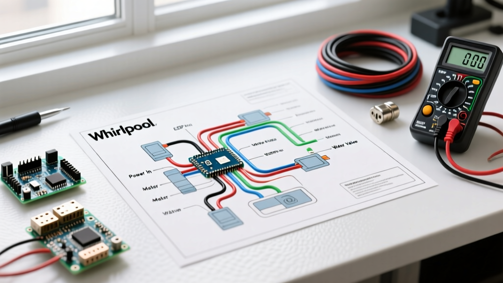

Introduction to Whirlpool Ice Maker Electrical Systems
When your refrigerator stops producing ice, the culprit is rarely a simple lack of water. Modern ice production relies on a precise orchestration of thermistors, solenoids, synchronous motors, and logic boards. To diagnose these failures accurately, you must understand how to read the wiring diagram for Whirlpool ice maker assemblies. Whether you are working on a classic mechanical modular unit like the Whirlpool 2198597 or a modern electronic assembly like the W10873791 found in current 2026 French-door models, the schematic is your ultimate troubleshooting map. This guide breaks down the electrical pathways, component specifications, and real-world failure modes that service technicians use every day.
Safety Protocols Before Probing the Schematic
Before you pull out your multimeter and start tracing wires, strict safety protocols must be followed. According to the Electrical Safety Foundation International (ESFI), appliance repair accounts for thousands of household electrical shocks annually. Always execute a proper Lockout/Tagout (LOTO) procedure:
- Disconnect Power: Unplug the refrigerator or trip the dedicated 15A/20A breaker at the main panel.
- Shut Off Water: Close the saddle valve or inline shutoff valve supplying the 1/4-inch water line.
- Capacitor Discharge: Wait at least 5 minutes after disconnecting power before probing the main control board (PCB) to allow high-voltage capacitors to discharge.
Decoding the Wiring Diagram for Whirlpool Ice Maker Models
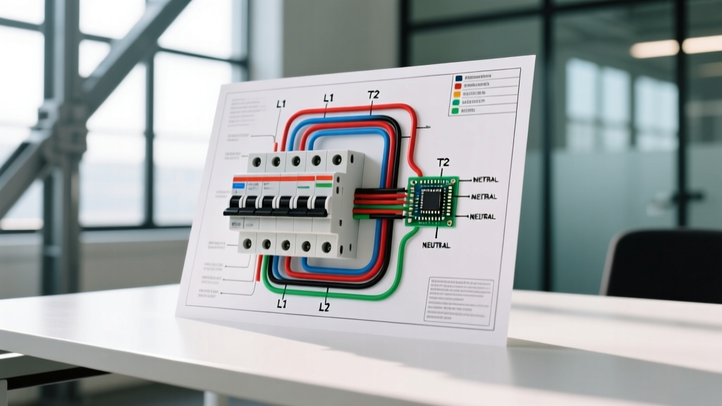
Whirlpool schematics use standardized line diagrams. The heavy lines on the left and right represent your main power supply: L1 (Line 1, 120V AC)N (Neutral) on a white wire. The green or bare copper wire is your chassis ground. Every component in the ice maker circuit is drawn as a switch, coil, or resistor bridging these two lines.
Mechanical vs. Electronic Control Architectures
Understanding the generation of your ice maker is critical for reading the diagram:
- Classic Modular (e.g., 2198597): These use a 120V AC synchronous harvest motor, a mechanical cam, and a bi-metal thermostat. The wiring diagram is straightforward, consisting mostly of high-voltage AC switch legs. The thermostat acts as the primary switch, closing at 15°F (-9°C) to allow the 120V AC heater to energize and melt the ice shell.
- Modern Electronic (e.g., W10873791): These units feature a localized low-voltage DC logic board. The main refrigerator PCB sends a 12V DC signal to the ice maker harness. The wiring diagram will show a mix of 120V AC (for the mold heater and water valve) and low-voltage DC communication lines (often red, orange, or yellow wires) that report thermistor temperatures and motor position back to the main board.
Component-by-Component Electrical Specifications
When tracing the wiring diagram, you need to know the expected electrical values to determine if a component is healthy or failed. Below is the diagnostic matrix for standard Whirlpool ice maker components. These values apply to most side-by-side and French-door models manufactured between 2015 and 2026.
| Component | Expected Resistance (Ohms) | Operating Voltage | Common Failure Symptom |
|---|---|---|---|
| Mold Heater | 100Ω - 150Ω | 120V AC | Ice cubes stuck in tray; motor hums but won't turn. |
| Harvest Motor | 4,400Ω - 8,000Ω | 120V AC | No movement; ice maker appears completely dead. |
| Water Inlet Valve | 200Ω - 500Ω | 120V AC | No water filling mold; hollow or missing cubes. |
| Bi-Metal Thermostat | 0Ω (Closed below 15°F) | 120V AC (Switch) | Unit never initiates a harvest cycle. |
| Thermistor (Electronic) | 11kΩ - 13kΩ (at 77°F) | 5V DC | Main board throws 'Sensor Error' code; no cycling. |
Pro Tip: Always use a True-RMS multimeter (like the Fluke 117) when testing the water inlet valve solenoid or the main board outputs. Standard averaging multimeters can give false readings on the rapid-switching triacs found on modern Whirlpool control boards.
Step-by-Step Troubleshooting Using the Schematic
Let us apply the wiring diagram to a real-world scenario: The ice maker is receiving power, the freezer is at 0°F, but the tray is empty and no harvest cycle is initiating.
Step 1: Verify the Bi-Metal Thermostat or Thermistor
On mechanical models, locate the bi-metal thermostat on the schematic. It sits in series with the harvest motor. If the freezer is cold but the thermostat contacts are pitted or stuck open, 120V AC cannot reach the motor. Use your multimeter in continuity mode. If the freezer is below 15°F and the meter reads 'OL' (Open Line), the thermostat is dead. On electronic models, test the thermistor resistance and compare it to the temperature/resistance chart provided in the Whirlpool Support Tech Sheets.
Step 2: Test the Water Inlet Valve Solenoid
If the ice maker cycles but no water enters, the schematic will direct you to the water inlet valve (often part number WPW10179146). Disconnect the wire harness and place your multimeter probes on the two solenoid terminals. A reading below 100Ω indicates a shorted coil; a reading above 1,000Ω indicates an open coil. Both require a $45 to $65 valve replacement.
Step 3: Diagnosing the Freezer Door Wire Harness (The Hidden Killer)
This is an edge case that stumps many DIYers. On French-door models like the WRX735SDHZ, the wire harness routes through the bottom freezer door hinge. Over 3 to 5 years, repeated opening and closing causes the 120V AC and 12V DC signal wires to fatigue and snap internally, even if the outer PVC insulation looks pristine. If your wiring diagram shows voltage leaving the main board but arriving at 0V at the ice maker plug, perform a 'wiggle test' on the door hinge harness while monitoring continuity. A replacement door harness (part number W11416383) typically costs between $60 and $85 and resolves this phantom power loss.
Advanced Diagnostics: The Forced Harvest Mode
Most modern Whirlpool electronic ice makers feature a diagnostic 'Forced Harvest' mode to bypass the thermistor and thermostat logic. By consulting the wiring diagram and the tech sheet hidden inside the front kickplate, you can usually trigger this mode by pressing the freezer door light switch three times within five seconds. This forces the main board to send 120V AC directly to the harvest motor and heater. If the unit harvests in forced mode but not in normal mode, your wiring is intact, and the fault lies with a failed temperature sensor or a corrupted main control board.
Frequently Asked Questions
Can I bypass the ice maker thermostat to keep it running?
Never bypass the bi-metal thermostat or thermistor by jumping the wires. The thermostat acts as a critical safety cutoff. If the mold heater energizes without the thermostat regulating the temperature, the plastic ice mold will melt, potentially causing a short circuit or an electrical fire. Always refer to RepairClinic diagnostic guides for safe testing procedures.
Why does my wiring diagram show a 12V DC line?
Newer Whirlpool models utilize a localized DC logic board inside the ice maker housing to save space and reduce high-voltage routing inside the freezer compartment. The main board steps down 120V AC to 12V DC to power the optical sensors and micro-switches, while still switching 120V AC for the high-draw heater and motor via internal relays.
What wire gauge is used in the ice maker harness?
The main 120V AC supply lines typically use 18 AWG stranded copper wire, which is rated for up to 16 amps—more than enough for the ice maker's maximum draw of roughly 3 to 4 amps during the heater cycle. Low-voltage sensor wires are usually 22 AWG.