
The Mobile HVAC Paradigm Shift in 2026
Historically, large Class A motorhomes, luxury fifth wheels, and custom Skoolie conversions relied on dual 15,000 BTU rooftop air conditioning units. However, as off-grid vehicle builds become more sophisticated, builders are increasingly adapting residential ducted systems for mobile use. If you are searching for a wiring diagram for central air conditioner setups in a vehicle, you are likely dealing with a 1.5-ton to 2-ton residential split or ducted system (such as the Pioneer 18,000 BTU ducted series or Senville Aura) powered by a high-capacity lithium battery bank.
Wiring a residential central AC into a vehicle introduces massive electrical hurdles: high Locked Rotor Amps (LRA), 240V split-phase requirements, and strict mobile grounding codes. According to the U.S. Department of Energy, modern central air conditioners are vastly more efficient than older models, but their startup surge currents can still destroy undersized mobile inverters. This guide provides a comprehensive, vehicle-specific wiring architecture to safely integrate a central AC system into your RV or bus conversion.
Sizing the Inverter and Battery Bank for Central Air
Before pulling a single wire, your power architecture must be validated. A standard 1.5-ton central air compressor requires roughly 1,800W to 2,200W of continuous running power, but the startup surge (LRA) can spike to 95 Amps at 240V (over 22,000W for a fraction of a second).
- The Inverter: You need a minimum of a 48V 5000VA Pure Sine Wave Inverter/Charger (e.g., Victron Quattro 48/5000 or MultiPlus-II 48/5000). Modified sine wave inverters will destroy the compressor windings and control boards.
- The Battery Bank: A minimum of 400Ah at 48V (or 800Ah at 24V) LiFePO4 is required to sustain the voltage sag during compressor startup without triggering the BMS low-voltage disconnect.
- The Secret Weapon (Soft Starter): Installing a Micro-Air EasyStart or SoftStartRV device is non-negotiable. These devices reduce the LRA surge by up to 65%, dropping a 95A spike down to a manageable 32A, allowing a 5000W inverter to start the compressor seamlessly.
Step-by-Step Wiring Diagram for Central Air Conditioner (RV Application)
Below is the logical wiring flow for a 240V split-phase central AC system adapted for a large vehicle. Always refer to the NFPA 70 National Electrical Code (NEC), specifically Article 551 for Recreational Vehicles, regarding grounding and bonding requirements.
Phase 1: DC Battery to Inverter
- Run 2/0 AWG stranded copper welding cable from the LiFePO4 battery bank busbars to the inverter DC terminals.
- Install a 250A Class T fuse on the positive cable within 18 inches of the battery terminal.
- Crimp all ring terminals using a hydraulic crimper and torque to the manufacturer's specification (typically 12 Nm for Victron 2/0 lugs).
Phase 2: AC Output to the Soft Starter & Compressor
Residential central ACs require two hot legs (L1 and L2), a neutral, and a ground. Your inverter must be configured for 120/240V split-phase output.
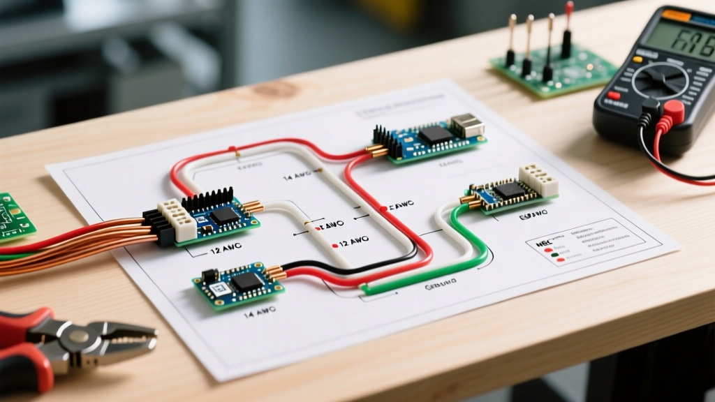
- From the inverter's AC Out terminals, run 10 AWG stranded THHN wire (Black for L1, Red for L2, White for Neutral, Green for Ground) to a double-pole 30A breaker in your main AC distribution panel.
- From the breaker, route the 4-wire setup to the Soft Starter module mounted directly adjacent to the outdoor compressor unit.
- Wire the Soft Starter outputs directly to the compressor's contactor and run capacitor terminals, following the specific color-coded schematic provided by the soft start manufacturer.
Phase 3: Thermostat and Low-Voltage Control Wiring
The indoor air handler and the outdoor condenser must communicate. In a vehicle, running standard 18 AWG thermostat wire through metal chassis walls can lead to chafing and short circuits.
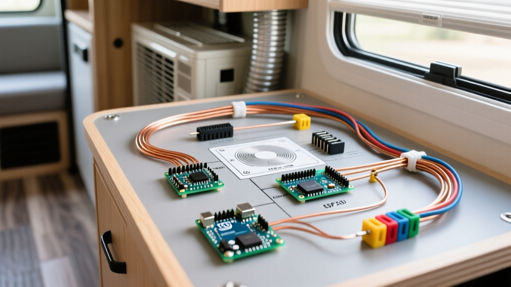
- Use 18/5 shielded thermostat wire routed through split-loom corrugated tubing to protect against vibration and metal edges.
- Connect the standard 24V control circuit: R (Power), Y (Compressor), G (Fan), W (Heat), and C (Common).
- Ensure the air handler's internal transformer is powered by the inverter's dedicated 120V AC circuit to maintain the 24V control signal.
Expert Tip: In mobile environments, vibration loosens standard wire nuts. Use WAGO 221 lever-nuts or marine-grade heat-shrink ring terminals for all 120V/240V AC junctions inside the vehicle to ensure fire-safe, vibration-proof connections.
Mobile HVAC Wire Gauge & Breaker Matrix
Selecting the correct wire gauge is critical to preventing voltage drop, which is the number one killer of mobile HVAC compressors. The table below outlines sizing for a standard 1.5-ton central system in a vehicle.
| Circuit Segment | Wire Gauge (Copper) | Breaker Size | Max Run Length (One Way) |
|---|---|---|---|
| Battery to Inverter (48V DC) | 2/0 AWG Stranded | 250A Class T Fuse | 10 feet |
| Inverter to AC Panel (240V AC) | 10 AWG Stranded THHN | 30A Double-Pole | 25 feet |
| AC Panel to Compressor (240V AC) | 10 AWG Stranded THHN | 30A Double-Pole | 20 feet |
| Air Handler Blower (120V AC) | 12 AWG Stranded THHN | 15A Single-Pole | 30 feet |
| Thermostat Control (24V DC) | 18 AWG Shielded (5-wire) | N/A (Control Circuit) | 50 feet |
Real-World Failure Modes & Edge Cases
When adapting residential HVAC for mobile use, builders frequently encounter edge cases that standard home wiring diagrams do not address. For deeper system design principles, the Victron Energy Wiring Unlimited Guide is an essential resource for mobile power architectures.
1. Chassis Ground vs. Neutral Bonding
In a residential home, the neutral and ground are bonded at the main panel. In an RV or Skoolie, if you are using an inverter/charger with an internal transfer switch (like the Victron Quattro), the neutral-to-ground relay must be configured correctly. If the inverter bonds neutral to ground internally while connected to shore power (which also bonds them), you create a parallel neutral path, tripping GFCI breakers and shore power pedestals. Set your inverter's ground relay to 'Auto' or disconnect the shore power ground bond when running off-grid.
2. Harmonic Distortion and Control Board Failures
Modern central air conditioners use variable-speed ECM blower motors and smart control boards. These components are highly sensitive to Total Harmonic Distortion (THD). If your inverter outputs anything greater than 5% THD, the HVAC control board will throw a fault code and refuse to engage the contactor. Always verify your inverter is outputting a pure sine wave (<3% THD) using an oscilloscope or high-end multimeter before energizing the HVAC system.
3. Condensate Drain Routing in Transit
While not strictly electrical, the condensate drain line must be wired with a 12V DC safety float switch. If the vehicle is parked off-level and the drain pan overflows, the float switch must interrupt the 24V thermostat 'Y' wire, killing the compressor to prevent catastrophic water damage to the vehicle's subfloor and battery banks.
Frequently Asked Questions
Can I run a central air conditioner on a standard 30A RV shore power plug?
No. A standard 30A RV plug provides 120V single-phase power (3,600W total). A residential central AC requires 240V split-phase power. You must be connected to a 50A RV shore power pedestal (which provides two 120V legs for 240V capability) or use a 48V inverter system to generate the 240V split-phase power from your battery bank.
Do I need a soft starter if I have a massive battery bank?
Yes. Even if you have 1000Ah of lithium batteries, the bottleneck is the inverter's peak surge capacity. A 5000W inverter can typically surge to 10,000W for a few seconds, but a central AC compressor can demand over 20,000W at startup. The soft starter is required to keep the surge demand within the inverter's physical limits.
What is the best wire type for vehicle HVAC wiring?
Never use solid core Romex (NM-B) in a vehicle. The constant vibration and chassis flex will cause solid copper wires to work-harden, snap, and arc inside the walls. Always use stranded copper wire with THHN or marine-grade tinned insulation for all AC and DC runs.