
Introduction to Fluorescent Ballast Safety and Compliance
Understanding the correct wiring diagram for fluorescent ballast systems is not just about making the lights turn on; it is a critical exercise in electrical safety and code compliance. Despite the industry's gradual shift toward LED retrofits, millions of T8 and T5 fluorescent fixtures remain in active commercial, industrial, and educational facilities. Improper ballast wiring is a leading cause of electrical fires, arc faults, and premature lamp failure. In 2026, electrical inspectors are strictly enforcing National Electrical Code (NEC) guidelines regarding luminaire wiring, thermal protection, and grounding.
This comprehensive guide breaks down the anatomy of a compliant fluorescent ballast wiring diagram, detailing exact wire gauges, stripping measurements, and NEC mandates to ensure your installation is safe, efficient, and inspection-ready.
The NEC Code Framework: Articles 410 and 250
Before touching a single wire nut, an electrical professional must understand the governing codes. The installation of fluorescent luminaires falls primarily under NEC Article 410 (Luminaires, Lampholders, and Lamps) and NEC Article 250 (Grounding and Bonding). According to the National Fire Protection Association (NFPA 70), all ballasts must be thermally protected and securely grounded to the metal chassis of the fixture.
Thermal Protection Mandates (NEC 410.73)
NEC 410.73 requires that fluorescent ballasts installed in built-in or recessed luminaires be thermally protected. Modern electronic ballasts, such as the Philips Advance ICN-2P32-N or the Keystone KTEB-232-1-TP, feature internal Class P thermal protectors. If the ballast reaches 194°F (90°C), the protector opens the circuit, preventing a fire. Bypassing or altering this internal wiring is a severe code violation that voids UL listings and compromises facility insurance.
Decoding the Wiring Diagram for Fluorescent Ballast Systems
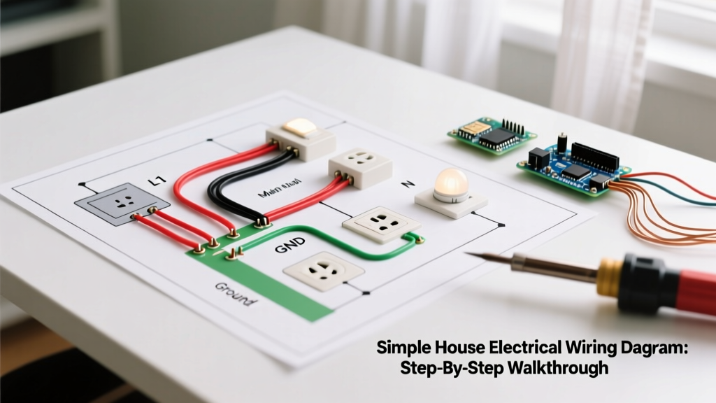
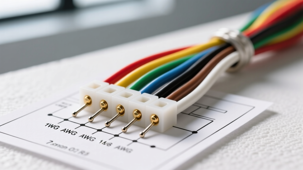
A standard wiring diagram for fluorescent ballast setups relies on a strict color-coding system. Deviating from these colors or misinterpreting the diagram leads to crossed phases, unlit lamps, or catastrophic ballast failure. Below is the universal color code for standard 120V-277V electronic T8 instant-start ballasts.
| Wire Color | Function | Connection Point | NEC / Safety Note |
|---|---|---|---|
| Black | Un-grounded (Hot) Line | Switch Leg / Branch Circuit | Must be connected to the breaker-controlled hot wire. |
| White | Grounded (Neutral) Line | Branch Circuit Neutral | NEC 200.2 requires the neutral to be identified and continuous. |
| Blue & Red | Lamp Output (High Voltage) | Lampholders (Tombstones) | High-frequency, high-voltage output. Requires 18 AWG minimum, 600V rated wire. |
| Green / Bare | Equipment Grounding | Fixture Chassis / Ground Screw | Mandatory per NEC 250.4. Must have low impedance to the panel. |
Step-by-Step Compliant Wiring Procedure
Executing the wiring diagram for a fluorescent ballast requires precision. Follow this step-by-step protocol to ensure compliance with both safety standards and manufacturer specifications.
Step 1: Lockout/Tagout (LOTO) and Verification
Never rely solely on a wall switch to de-energize a lighting circuit. Per OSHA's Control of Hazardous Energy standards, you must turn off the dedicated breaker at the main distribution panel and apply a physical lock and tag. Use a CAT III or CAT IV non-contact voltage tester and a digital multimeter to verify zero voltage between the hot and neutral, and hot and ground, before exposing any conductors.
Step 2: Wire Preparation and Stripping
The most common cause of ballast failure is improper wire preparation. Ballast lead wires are typically 18 AWG solid or stranded copper.
- Strip Length: Strip exactly 1/2 inch (13mm) of insulation. Stripping too much exposes live copper, risking a short against the metal ballast casing. Stripping too little results in insulation being crimped inside the wire nut, causing a high-resistance connection and eventual thermal meltdown.
- Branch Circuit Wires: If the branch circuit is 14 AWG (15A breaker) or 12 AWG (20A breaker), use a stepped wire stripper to ensure the larger gauge wire is properly prepped for the wire nut.
Step 3: Making the Connections
Connect the ballast's white wire to the circuit neutral using a UL-listed wire nut (e.g., Ideal SureConnect or 3M Performance Plus). Twist the wire nut clockwise until the wires inside the connector begin to twist together, ensuring a torque-tight mechanical and electrical bond. Repeat for the black (hot) wire. Finally, attach the green grounding pigtail from the ballast to the metal fixture chassis using a 10-32 hex head machine screw and a star washer to bite through any paint or powder coating, ensuring a true metal-to-metal ground path.
Common Code Violations and Failure Modes
Even experienced electricians can make errors when rushing through commercial lighting retrofits. Be vigilant against these frequent code violations:
CRITICAL SAFETY WARNING: Never use the metal conduit (EMT) or the fixture suspension wire as the sole equipment grounding conductor for the ballast. NEC 250.118 allows EMT as a ground, but a dedicated copper equipment grounding conductor (EGC) pulled inside the conduit is required for reliable fault clearing and to prevent the fixture chassis from becoming energized during a ballast internal fault.
- Over-torquing Lampholder Screws: When wiring the blue and red output leads to the tombstones (lampholders), over-tightening the terminal screws can crack the polycarbonate housing. This leads to arcing when the high-voltage starting pulse (up to 600V) is applied.
- Mixing Lamp Types: Wiring a T12 rapid-start ballast to T8 lamps, or vice versa, alters the starting voltage and current. This violates the UL listing of the luminaire and causes rapid cathode degradation, leading to blackened lamp ends and flickering.
- Missing Fixture Whip Grounds: In suspended ceiling installations using flexible metal conduit (FMC) whips, the internal green ground wire must be bonded to both the junction box and the fixture. FMC alone is only permitted as a ground for lengths under 6 feet and under specific amperage limits.
The 2026 Context: LED Ballast Bypass (Type B) Code Implications
As facilities upgrade to save energy, many are bypassing the fluorescent ballast entirely to install Single-Ended or Double-Ended Type B LED tubes. When you remove the ballast from the wiring diagram, the code requirements shift. According to the U.S. Department of Energy's Solid-State Lighting guidelines, bypassing a ballast requires the installation of new, UL-listed lampholders (tombstones) rated for the line voltage, and a prominent warning label must be affixed to the outside of the fixture. If you leave the old fluorescent lampholders in place during a single-ended LED retrofit, the exposed pins on the opposite end of the tube become a severe 120V/277V shock hazard, a direct violation of NEC 410.6.
Expert Troubleshooting & Safety FAQs
Why is my newly wired fluorescent fixture humming loudly?
A loud hum usually indicates a magnetic ballast that is not securely fastened to the metal fixture pan, causing harmonic vibration. If you are using an electronic ballast (which operates at 20kHz+ and should be silent), humming indicates internal component failure or that the ballast is being operated on a dimmer circuit, which electronic ballasts cannot tolerate unless specifically rated for it.
Can I wire two ballasts to a single 15-amp breaker?
Yes, but you must calculate the total load. A standard 2-lamp T8 electronic ballast draws approximately 0.25 amps at 277V or 0.55 amps at 120V. NEC Article 210.20 requires that continuous loads (lights on for 3+ hours) not exceed 80% of the breaker rating. On a 15A/120V breaker, your maximum continuous load is 12A, allowing for roughly 21 standard two-lamp T8 fixtures per circuit.
What wire gauge should I use for the blue and red output leads?
Always use a minimum of 18 AWG, 600V-rated, 105°C stranded copper wire for the output leads running from the ballast to the lampholders. If the run from the ballast to the tombstone exceeds the length of the factory-provided leads, do not just twist wires together and tape them. Use an inline, fully insulated, heat-shrink solder sleeve or a UL-listed crimp connector to extend the high-frequency output wires safely.