
The Anatomy of a Modern 48V Golf Cart Drivetrain
Transitioning to or maintaining a 48-volt architecture is the definitive standard for modern electric golf carts, offering superior torque, hill-climbing capability, and efficiency compared to legacy 36V systems. Whether you are retrofitting a classic Club Car DS, upgrading a Yamaha Drive2, or troubleshooting an EZGO RXV, understanding the exact wiring diagram for 48 volt golf cart setups is critical. A single misplaced phase wire or an undersized solenoid feed can result in catastrophic controller failure or severe fire hazards.
In this comprehensive motor wiring tutorial, we dissect the high-current and low-voltage logic circuits required to safely wire a 48V system. We will reference modern aftermarket standards, including the widely used Navitas 48V 600A and Alltrax XCT48600 controllers, paired with high-torque AC induction motors like the KDS 10kW.
Power Source Selection: Lead-Acid vs. Lithium (2026 Market Data)
Before routing a single cable, your battery bank dictates your wire gauge and fuse sizing. The market has shifted heavily toward LiFePO4 (Lithium Iron Phosphate) due to drastic weight reductions and depth-of-discharge (DoD) advantages.
| Specification | Traditional Lead-Acid (6x 8V) | Modern LiFePO4 (1x 48V 105Ah) |
|---|---|---|
| Nominal Voltage | 48V (51.8V fully charged) | 48V (54.7V fully charged) |
| Total Weight | ~310 lbs | ~75 lbs |
| Usable Capacity (DoD) | 50% (~100Ah usable) | 80-100% (~95Ah usable) |
| Average 2026 Cost | $1,100 - $1,400 | $2,100 - $2,400 |
| Main Fuse Requirement | 250A ANL Fuse | 150A ANL Fuse (w/ integrated BMS) |
Decoding the Wiring Diagram for 48 Volt Golf Cart Systems
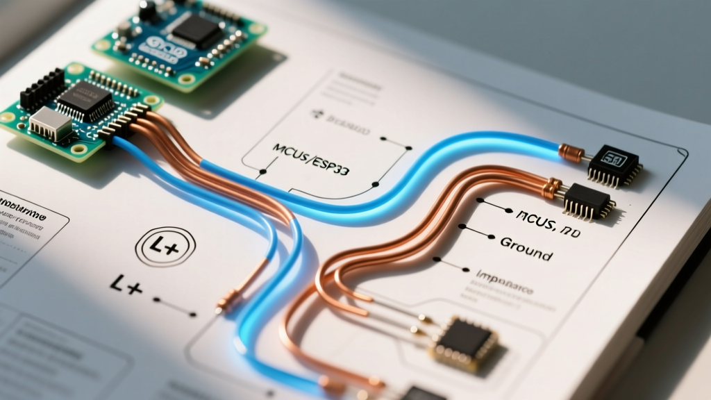
A proper 48V wiring diagram is divided into two distinct domains: the high-current traction circuit and the low-voltage logic/throttle circuit. Mixing these domains or routing them in parallel without shielding is the leading cause of erratic throttle behavior and controller burnout.
Step 1: High-Current Battery and Solenoid Routing
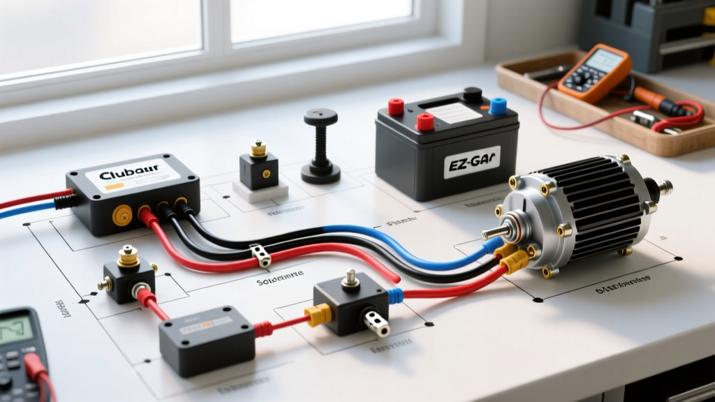
The main solenoid acts as the heavy-duty relay connecting the battery bank to the motor controller. For a 600A peak system, you must use 1/0 AWG or 2 AWG ultra-flexible marine-grade copper wire (e.g., 105°C rated welding cable).
- Main Positive Feed: Run 1/0 AWG wire from the battery positive terminal through a 250A (Lead-Acid) or 150A (Lithium) ANL fuse, directly to the large terminal on the line side of the main solenoid.
- Solenoid to Controller: Run another 1/0 AWG cable from the load side of the solenoid to the B+ (Battery Positive) terminal on the motor controller.
- The Pre-Charge Circuit (Critical): You must wire a 470-Ohm, 3-Watt pre-charge resistor between the line and load sides of the main solenoid. When the key turns on, this resistor slowly charges the controller's massive internal capacitors. Skipping this resistor will cause a massive inrush current that will instantly weld the solenoid contacts shut, creating a runaway cart scenario.
- Grounding: Run 1/0 AWG from the battery negative to the controller B- terminal. Ensure the chassis is bonded to this main negative bus using a minimum 4 AWG strap.
Step 2: Controller to Motor Phase and Sensor Wiring
Modern 48V carts utilize 3-phase AC induction motors. The controller converts the DC battery voltage into a simulated 3-phase AC sine wave.
- Phase Wires (U, V, W): Use 2 AWG wire for the three phase connections. It is imperative that all three phase wires are cut to the exact same length. A variance in length alters the electrical resistance and inductance per phase, causing the controller to read imbalanced current draws, which triggers thermal rollback or fault codes.
- Hall Effect Sensors: The motor contains three Hall sensors to report rotor position back to the controller. These use thin 18 AWG to 22 AWG wires (typically 5V, Ground, Phase A, Phase B, Phase C). Warning: Never zip-tie the Hall sensor harness directly to the thick phase wires. The electromagnetic interference (EMI) generated by the 600A PWM switching will induce phantom voltage in the sensor lines, causing the motor to violently shudder or over-rev.
Step 3: Low-Voltage Throttle and Logic Circuits
The throttle mechanism varies by manufacturer. Club Car Precedent and Onward models use a MCOR (Motor Controller Output Regulator), which is a non-contact Hall-effect pedal assembly outputting a 0V to 5V (or 0V to 3.3V) analog signal. Older EZGO models use an ITS (Inductive Throttle Sensor).
Wire the throttle signal, 5V reference, and ground using an 18 AWG shielded 3-conductor cable. Connect the shield drain wire to the controller's logic ground only—never at the pedal end—to prevent ground loops.
Wire Gauge and Crimping Standards
Amateur wiring jobs frequently fail at the crimp connections due to improper tooling. According to the NFPA 70 (National Electrical Code), wire ampacity must be matched to the continuous load, but in golf cart applications, peak surge loads dictate the sizing. Furthermore, adherence to the IPC/WHMA-A-620 standard for cable assemblies ensures mechanical integrity.
Pro-Tip for High-Current Lugs: Do not use standard pliers or hammer crimpers for 2 AWG or 1/0 AWG lugs. You must use a 6-ton hydraulic crimper with the correct hexagonal die. After crimping, seal the lug with adhesive-lined, dual-wall heat shrink (3M or Raychem). The internal adhesive melts and seals out moisture, preventing the green copper oxidation that causes high-resistance failures in humid environments.
Real-World Failure Modes and Diagnostics
When troubleshooting a 48V golf cart that refuses to move or operates erratically, rely on data, not guesswork. Use a high-quality digital multimeter (DMM) capable of logging min/max voltage.
1. The Voltage Drop Test (Finding Hidden Resistance)
A cart that bogs down under heavy load often suffers from a 'ghost' connection. With the cart's drive wheels safely elevated and the motor engaged under load, measure the DC voltage drop across every single connection (from battery post to lug, across the fuse, across the solenoid, and into the controller).
The Rule: A healthy, properly crimped connection should show a voltage drop of less than 0.05V. If you read 0.2V or higher across the main solenoid contacts while engaged, the internal contacts are pitted and the solenoid must be replaced immediately.
2. Controller Thermal Rollback
If your Navitas or Alltrax controller limits speed after 10 minutes of driving, check the motor temperature sensor wiring. If the sensor wire is pinched against the chassis and shorting to ground, the controller will falsely read that the motor is at 150°C+ and initiate protective thermal rollback. Inspect the entire sensor harness for abrasion.
3. Solenoid 'Click' but No Movement
If you hear the solenoid click (meaning the low-voltage logic and pedal micro-switches are working) but the motor doesn't spin, the issue is almost always in the high-current path. Check the 48V feed to the controller's B+ terminal. If B+ reads 0V after the click, your pre-charge resistor may be blown, or the solenoid's internal copper contact disc has failed to bridge the gap.
Final Safety and Commissioning Checklist
Before dropping the cart off the jacks and taking your first test drive, complete this final verification matrix:
- Tow/Run Switch: Ensure the controller's Tow/Run toggle is in the 'Run' position. Leaving it in 'Tow' disables the regenerative braking and high-speed logic.
- Jacking Mode: If using a lithium battery with a smart BMS, ensure you have not triggered the BMS transport/jacking mode, which limits output to 10A.
- Reverse Buzzer: Verify the reverse alarm triggers correctly; this is wired directly to the controller's F/R (Forward/Reverse) logic output.
- Throttle Calibration: Use the manufacturer's Bluetooth app or programming dongle to calibrate the MCOR/ITS deadzones. Set the minimum deadzone to 10% and maximum to 90% to account for mechanical wear in the pedal box over time.
By strictly following this wiring diagram for 48 volt golf cart architectures and respecting the physics of high-amperage DC circuits, you ensure a reliable, high-torque drivetrain capable of handling the demands of modern street-legal LSV conversions and heavy off-road use.