
Decoding Residential Electrical Wiring Diagrams for Motor Circuits
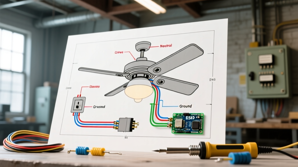
Interpreting residential electrical wiring diagrams is a foundational skill for any DIYer, HVAC technician, or apprentice electrician working on home motor circuits. Unlike standard lighting or receptacle wiring, motor circuits involve high inrush currents, specialized starting mechanisms, and strict adherence to the National Electrical Code (NEC). Whether you are replacing a submersible well pump or troubleshooting an air handler blower, understanding the schematic symbols and terminal designations is critical for safety and system longevity.
In this comprehensive tutorial, we will dissect the most common motor wiring configurations found in modern homes, bridging the gap between legacy Permanent Split Capacitor (PSC) motors and modern Electronically Commutated Motors (ECM), while providing exact wire gauge requirements and troubleshooting frameworks.
The Modern Shift: PSC vs. ECM Blower Motors
Historically, residential HVAC systems relied on PSC motors. However, driven by Department of Energy (DOE) efficiency mandates, the industry has largely transitioned to ECM technology. When reviewing updated residential electrical wiring diagrams, you must know which motor type you are dealing with, as the wiring architecture is fundamentally different.
| Feature | PSC Motor (Legacy) | ECM Motor (Modern Standard) |
|---|---|---|
| Speed Control | Fixed speeds via multi-tap winding | Variable speed via internal microprocessor |
| Wiring Harness | Standard Romex to contactor/relay | Main power harness + 16-pin low-voltage control harness |
| Efficiency | ~45% to 60% | Up to 80% (DOE Premium Efficiency) |
| Common Models | Genteq 5121, Fasco D-Series | Genteq ECM 3.0, Regal Rexnord V-S |
| Failure Mode | Bad run capacitor, burnt winding | Failed control module, thermistor fault |
According to the U.S. Department of Energy's Motor Systems guidelines, ECM motors can reduce residential HVAC blower energy consumption by up to 33% compared to standard PSC models, making them the default in 2026 building code compliance.
Anatomy of an ECM Wiring Harness
When looking at the schematic for an ECM motor (such as the ubiquitous Genteq X13 or 3.0), you will notice two distinct harnesses. The 5-pin main power harness supplies line voltage, while the 16-pin control harness receives 24VAC signals from the furnace control board to dictate torque and RPM.
- Pin 1 (Black): 120VAC or 240VAC Hot (Line 1)
- Pin 2 (White): Neutral
- Pin 3 (Red): 208/230VAC Hot (Line 2) - Only used on 240V systems; capped on 120V.
- Pin 4 (Yellow): Equipment Ground
- Pin 5 (Green): Equipment Ground
Expert Warning: Never attempt to ohm out an ECM motor module with a standard multimeter while the 16-pin harness is connected. The internal microprocessor will yield false short-circuit readings. Always disconnect both harnesses and wait 5 minutes for internal capacitors to discharge before testing with a Fluke 87V or equivalent true-RMS meter.
Step-by-Step Tutorial: Wiring a 240V Submersible Well Pump
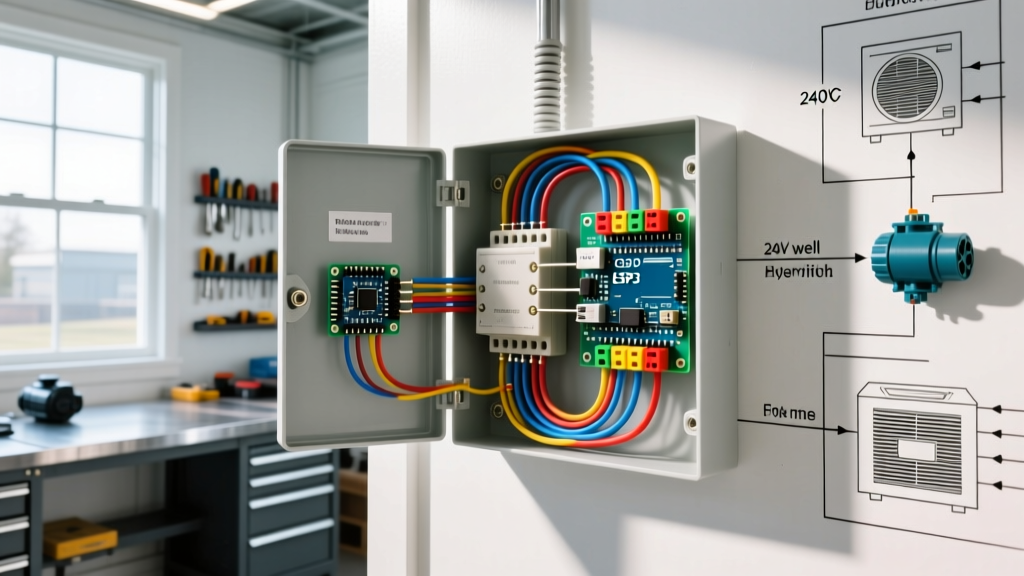
Water well systems represent some of the most demanding motor loads in a residential setting. A standard 3-wire, 1.5 HP, 230V submersible pump (such as those manufactured by Franklin Electric) requires a specialized control box mounted above ground. The residential electrical wiring diagrams for these systems revolve around managing the high Locked Rotor Amps (LRA) during startup.
Control Box Terminal Mapping
The control box houses a start capacitor (e.g., 105-126 MFD), a run capacitor (e.g., 15 MFD, 370VAC), and a potential relay (e.g., Supco SU series). Here is the precise wiring sequence:
- Line Voltage In: Connect the 240V feed from the double-pole breaker to the Line terminals on the pressure switch.
- Load to Control Box: Run a 10/3 UF-B or THHN in conduit from the pressure switch to the control box. Black to L1, Red to L2, White (re-marked Black) to L3, Green to Ground.
- Control Box to Pump (Drop Wire): Inside the box, the Black wire connects to the main run winding. The Red wire connects to the start winding via the potential relay and start capacitor. The Yellow wire connects to the common run winding. The Green wire bonds to the ground bus.
For exact schematic variations and torque specifications on terminal lugs, always refer to the Franklin Electric Technical Manuals, as miswiring the potential relay will result in the start capacitor exploding within seconds of energization.
Sizing Conductors and Breakers per NEC Article 430
One of the most common mistakes DIYers make when interpreting residential electrical wiring diagrams is sizing the breaker based on the motor's Full Load Amps (FLA). Motors draw 500% to 700% of their FLA for a fraction of a second during startup. If you size the breaker to the FLA, it will trip instantly.
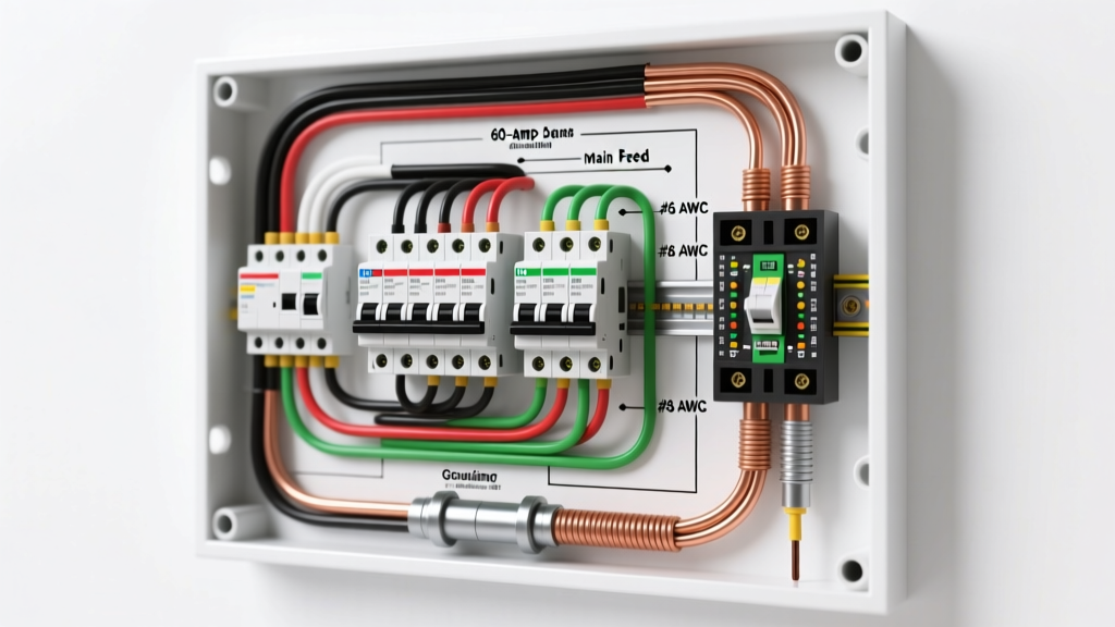
Under NEC Article 430.52, inverse-time circuit breakers can be sized up to 250% of the motor FLA to accommodate inrush current, while the wire is sized at 125% of the FLA per Article 430.22. As highlighted by EC&M's guide on NEC motor circuit requirements, proper coordination between the overload relay and the branch circuit breaker is mandatory.
| Motor HP | Voltage | FLA (Approx) | Min Wire Gauge (THHN/Cu) | Max Breaker Size (Inverse Time) |
|---|---|---|---|---|
| 1/2 HP | 230V | 4.9A | 14 AWG | 15A |
| 1 HP | 230V | 8.0A | 12 AWG | 20A |
| 1.5 HP | 230V | 10.0A | 10 AWG | 25A |
| 3 HP | 230V | 18.7A | 8 AWG | 50A |
Note: Always verify the exact FLA and Service Factor (SF) on the motor's physical nameplate, as manufacturer specifications supersede NEC generic tables.
Troubleshooting Common Motor Wiring Failures
Even with perfect adherence to residential electrical wiring diagrams, environmental factors and component degradation cause failures. Use this diagnostic framework before replacing expensive equipment.
1. Voltage Drop Under Load
If a well pump motor hums but fails to start, or an HVAC blower runs at reduced RPM, suspect voltage drop. Measure the voltage at the breaker, then at the motor terminals while the motor is attempting to start. A drop greater than 5% (e.g., below 218V on a 230V circuit) indicates undersized wire for the run length. For a 1.5 HP well pump located 250 feet from the panel, you must upsize from 10 AWG to 6 AWG copper to mitigate voltage drop.
2. Thermal Overload Tripping
Most residential motors feature an internal thermal overload protector. If the motor runs for 10 minutes and then dies, only to restart 30 minutes later, the overload is doing its job. Do not bypass this. Instead, check for:
- Restricted Airflow: Dirty HVAC filters causing the blower to overheat.
- Bad Run Capacitor: A weak capacitor (measured below 90% of its rated MFD using a multimeter's capacitance setting) forces the motor to draw excessive amperage, generating excess heat.
- Mechanical Binding: Seized bearings in exhaust fans or well pump impeller scale buildup.
3. ECM Communication Faults
If an ECM blower motor is completely dead, check the 5-amp automotive-style fuse on the furnace control board. A blown fuse often indicates a short in the 24VAC control harness. If the fuse is intact but the motor won't spin, use the manufacturer's diagnostic LED tool (e.g., the Genteq ECM TEComm tool). Plug it into the 16-pin port; if the LED flashes a specific fault code, the motor module (not the entire motor) can often be swapped out in the field for roughly $150 to $250, saving the cost of a full motor replacement.
Final Safety Protocols: LOTO and Capacitor Discharge
Working with motor circuits demands strict Lockout/Tagout (LOTO) procedures. Furthermore, start and run capacitors store lethal amounts of DC voltage even after the breaker is turned off. Always use a 20,000-ohm, 5-watt bleeder resistor across the capacitor terminals for 5 seconds before touching any wiring. Mastering residential electrical wiring diagrams is not just about making the right connections; it is about understanding the physics of the circuit to ensure you walk away safely after every repair.