
The Anatomy of an Emerson Electric Motor Wiring Schematic
When an HVAC system or industrial blower fails, the physical sticker on the motor housing is often faded by UV exposure and heat. In these critical moments, knowing how to interpret a standardized Emerson electric motor wiring schematic is the difference between a quick $20 capacitor swap and an unnecessary $800 motor replacement. Emerson (now largely operating under the Nidec umbrella for HVAC and industrial motors) designs its schematics around strict NEMA (National Electrical Manufacturers Association) color codes and terminal mapping. However, field technicians frequently misdiagnose open windings simply because they misread the multi-tap speed control nodes.
Unlike basic single-speed motors, modern Emerson schematics integrate thermal overload protectors, multi-speed winding taps, and complex capacitor circuits into a single dense diagram. This guide breaks down how to use these schematics for advanced multimeter diagnostics, focusing on real-world failure modes in ubiquitous models like the USR542 and 5KCP39PG.
Standard PSC Terminal Mapping and Color Codes
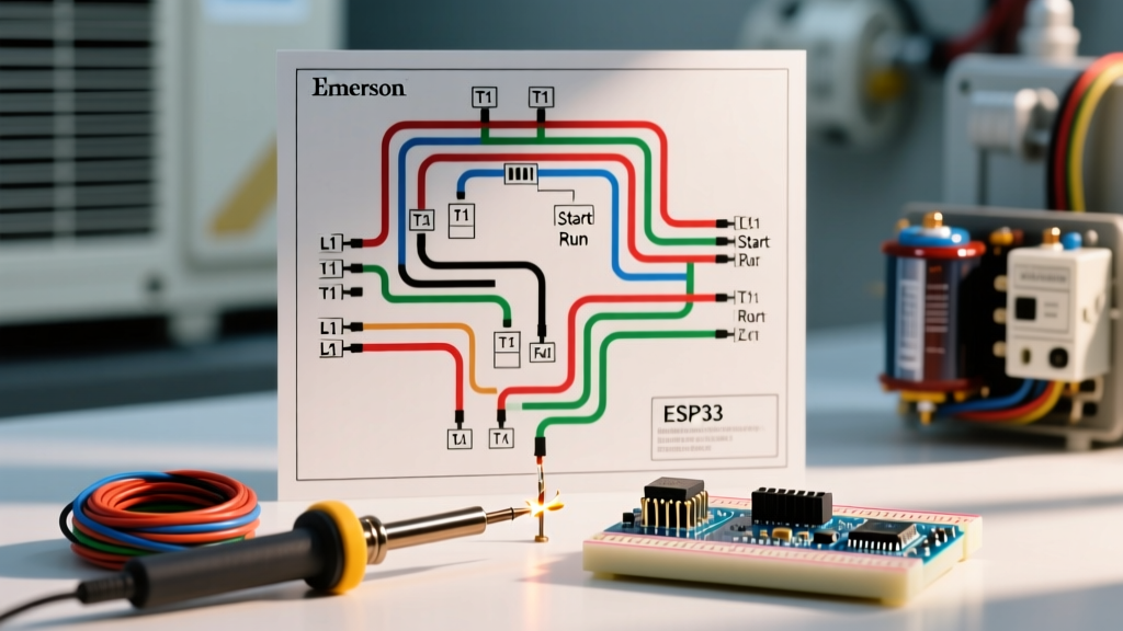
Before applying a multimeter, you must understand the baseline schematic logic for Emerson Permanent Split Capacitor (PSC) motors. The schematic will typically route power through the following standardized color-coded wires:
- White (Common): The main return path for both the start and run windings. Connects to the contactor or relay common terminal.
- Black (Run/High Speed): The primary run winding tap. In multi-speed schematics, this represents the highest RPM (lowest resistance path).
- Blue (Medium Speed) & Red (Low Speed): Additional run winding taps with progressively higher resistance to induce slip and lower fan RPM.
- Brown & Brown/White (Capacitor Circuit): These bypass the main power feed and connect directly to the run capacitor, completing the start winding circuit without relying on a centrifugal switch.
Pro Tip: Never connect line voltage to the Brown or Brown/White wires. The Emerson schematic routes these exclusively to the capacitor. Applying 240V here will instantly vaporize the start winding.
Real-World Troubleshooting: Emerson USR542 & 5KCP39PG
Let us apply the schematic to field diagnostics using two of the most common replacement motors in the industry.
Model 1: Emerson USR542 (Universal SureStart)
The USR542 is a 208-230V, 1/4 to 1 HP blower motor. Its schematic features a 4-speed tap (Black, Blue, Red, White/Low) and a built-in auto-reset thermal protector. If the USR542 is humming but not turning, the schematic directs you to check the thermal overload first. The overload is wired in series with the Common (White) wire. If your multimeter reads infinite resistance (OL) between White and Black, the thermal protector is tripped or permanently open. Allow 45 minutes for the bimetallic strip to cool before condemning the motor.
Model 2: Emerson 5KCP39PG (Condenser Fan Motor)
This 1/4 HP, 825 RPM condenser motor schematic is simpler but highly prone to capacitor-related failures. The schematic shows the Brown wire connecting to the 'Herm' (H) terminal of the dual run capacitor, and the Brown/White connecting to the 'C' (Common) terminal of the capacitor, not the line voltage common. A common wiring error here results in the motor running backward or failing to start, eventually tripping the internal overload.
Step-by-Step Winding Resistance Diagnostics
When the schematic indicates a potential winding failure, you must isolate the motor from all power and capacitors. According to Fluke's motor troubleshooting protocols, testing winding resistance requires a high-resolution multimeter capable of reading down to 0.1 ohms.
The Resistance Rule of Thumb
The schematic of any PSC motor dictates a strict mathematical relationship between the windings: Resistance (Start to Common) + Resistance (Run to Common) = Resistance (Start to Run).
| Multimeter Probes | Schematic Nodes | Expected Resistance | Diagnostic Meaning |
|---|---|---|---|
| Black to White | Run to Common | 1.8 Ω - 2.5 Ω | Healthy Run Winding |
| Brown to White | Start to Common | 4.5 Ω - 6.0 Ω | Healthy Start Winding |
| Black to Brown | Run to Start | 6.3 Ω - 8.5 Ω | Continuous Circuit (Sum of Run + Start) |
| Any Wire to Case | Windings to Ground | OL (Infinite) | No short to ground (Healthy) |
If your Black-to-Brown reading is lower than the sum of the other two, the schematic's internal wiring has a shorted turn between the start and run windings. The motor must be replaced.
Troubleshooting Matrix: Symptoms to Schematic Checks
Use this matrix to map physical symptoms directly to nodes on the Emerson electric motor wiring schematic.
| Field Symptom | Schematic Node to Investigate | Multimeter Test | Expected Result / Action |
|---|---|---|---|
| Motor hums, shaft locked | Brown / Brown-White (Cap) | Test Capacitor μF | Replace if >6% below rated μF |
| Runs on High, dies on Low | Red / Blue (Speed Taps) | Resistance to White | Check for open coil in tap winding |
| Stops after 10 mins, auto-restarts | White (Common Overload) | Amp Draw vs. FLA | Overload tripping; check for dirty blower wheel or low voltage |
| Runs backward | Brown / Brown-White | Visual Wiring Check | Capacitor wires swapped or start winding open |
Advanced Edge Cases: Multi-Tap Speed Control Failures
One of the most misunderstood aspects of the Emerson schematic is the 'missing speed' phenomenon. Technicians often assume the motor is dead if the medium speed (Blue) fails while high (Black) works.
Looking closely at the schematic, you will see that the speed taps are wound in series. If the Blue wire circuit is open, it means the physical copper wire inside the stator has broken between the High and Medium tap points. Because the Run winding is continuous, an open tap cannot be bypassed or repaired in the field. As noted by the experts at HVAC School's motor testing guides, attempting to jump out a broken speed tap by applying line voltage to a lower tap while the higher taps remain connected will result in severe back-EMF generation, leading to rapid insulation breakdown and catastrophic motor failure.
ECM Motors: When the Schematic Changes Completely
If you are troubleshooting an Emerson X13 or ProTech Electronically Commutated Motor (ECM), throw out the standard PSC resistance rules. The ECM schematic does not show simple copper windings; it maps a 5-pin low-voltage control connector (Tecomate) and a 16-pin Molex power connector.
Diagnostic Steps for Emerson ECM Schematics
- Verify High Voltage: Check for 208-240V across the L1 and L2 pins on the 16-pin Molex connector. The internal inverter requires this to power the DC bus.
- Verify 24VAC Control Signals: The schematic will show the 5-pin connector receiving 24VAC from the control board. Pin 1 (Comfort/R) and Pin 2 (Efficiency/E) dictate the motor's internal torque profile.
- The 'Spinning Freely' Test: Unlike PSC motors, an ECM should spin freely by hand when unpowered. If the shaft is stiff or 'cogging', the internal permanent magnets have detached, or the inverter bearings have seized. No schematic troubleshooting will save a mechanically locked ECM.
Essential Tooling for Schematic-Based Diagnostics
To properly execute the tests dictated by an Emerson electric motor wiring schematic, standard shop tools are insufficient. You must utilize:
- True-RMS Multimeter (e.g., Fluke 87V): Essential for accurate resistance readings below 1 ohm and measuring the precise 24VAC control signals on ECM models.
- Megohmmeter (Megger): For motors drawing high amperage without tripping the breaker, a 500V DC insulation resistance test is required. A healthy Emerson motor should read >100 Megohms to ground. Anything below 2 Megohms indicates moisture ingress or baked enamel insulation failure.
- Capacitor Tester with ESR: Measuring microfarads is not enough. High Equivalent Series Resistance (ESR) in a run capacitor will cause the Emerson start winding to overheat, even if the μF reading appears normal on a standard meter.
Summary
Mastering the Emerson electric motor wiring schematic transforms you from a parts-changer into a true diagnostic technician. By understanding the mathematical relationship between the start and run windings, respecting the thermal overload pathways, and recognizing the distinct architectural differences between PSC and ECM models, you can accurately isolate failures in minutes. Always de-energize the circuit, isolate the capacitor, and let the schematic guide your multimeter probes to the exact point of failure.