
Why Proper Wiring Matters for Electric Cooling Fans
Swapping a mechanical clutch fan for an electric setup is one of the most effective ways to reclaim parasitic horsepower—often freeing up 15 to 20 HP at the crank while improving low-speed cooling. However, an electric cooling fan is a massive inductive load. A standard 16-inch puller fan can draw 15 to 25 amps continuously, with inrush currents spiking up to 60 amps upon startup. Without a properly engineered auto electric fan wiring diagram, you risk melted harnesses, blown ignition switches, or catastrophic electrical fires.
In this comprehensive reference guide, we break down the exact schematic topology required to safely wire single and dual electric fans, integrate thermostatic controls, and select the correct wire gauges based on the SAE J1128 standard for automotive primary cables.
Core Components of an Auto Electric Fan Wiring Diagram
Before tracing the circuit paths, you must understand the specific heavy-duty components required for a reliable 2026 restomod or daily driver build. Never use standard low-current automotive toggle switches to power a fan directly.
The Bosch-Style Relay (The Heart of the Circuit)
The standard ISO mini relay (often called a Bosch-style relay) is mandatory. It isolates the high-amperage fan circuit from the low-amperage trigger circuit. You will need a heavy-duty 40A or 50A relay, such as the Bosch 0332014150. The pins are standardized:
- Pin 30: High-current 12V+ input (from the battery or main distribution block).
- Pin 87: High-current 12V+ output (to the fan motor).
- Pin 85: Coil ground (to chassis or engine block).
- Pin 86: Coil trigger 12V+ (from the thermostat switch or ECU).
Thermostatic Switches and Triggers
Thermostats act as the low-current switch that activates Pin 86. They come in two primary styles:
- Probe-Style: Slides into the radiator fins (e.g., Derale 16749). Easy to install but can be damaged during radiator removal.
- Threaded/Inline Style: Screws into a dedicated bung on the intake manifold or an inline coolant hose adapter (e.g., Hayden Automotive 3653). Highly accurate and physically robust.
Step-by-Step: Single Fan Wiring Diagram Explanation
For a single fan drawing under 30 amps, a standard 40A relay circuit is sufficient. Here is the exact path your wiring must follow:
- Power Feed: Run a 10 AWG TXL wire from the positive battery terminal to a 30A slow-blow fuse or circuit breaker (like a Bussmann CB181-30). From the breaker, run the wire to Relay Pin 30.
- Fan Feed: Run a 10 AWG wire from Relay Pin 87 directly to the positive terminal on the electric fan motor.
- Grounding the Fan: Run a 10 AWG ground wire from the fan's negative terminal directly to a clean, bare-metal grounding point on the engine block. Never rely on the aluminum radiator support for high-amp grounds.
- Trigger Circuit: Run an 18 AWG wire from an ignition-switched 12V source to one side of your thermostatic switch. Run another 18 AWG wire from the other side of the thermostat to Relay Pin 86.
- Relay Ground: Run an 18 AWG wire from Relay Pin 85 to a clean chassis ground.
Advanced Setup: Dual Fan Parallel Wiring Diagram
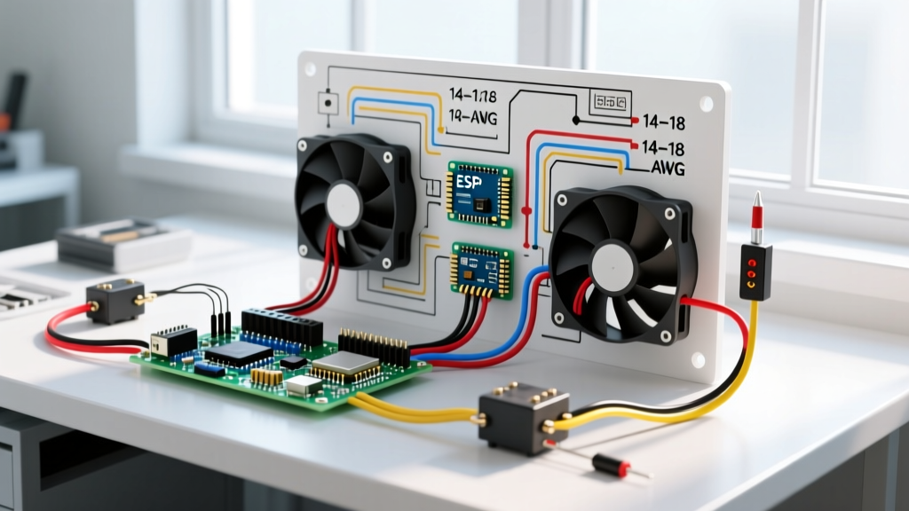
High-horsepower LS swaps or forced-induction builds often require dual fans (e.g., twin Spal 11-inch pullers). Wiring two fans to a single 40A relay will melt the internal contacts. You must use a parallel dual-relay topology.
Expert Tip: When wiring dual fans, use two separate relays triggered by the same thermostat switch. This ensures that if one relay fails, the other fan continues to cool the engine, preventing a catastrophic overheat event.
The Dual Fan Schematic:
- Run a heavy 8 AWG main power line from the battery to a 50A mega-fuse.
- Split the power line to feed Pin 30 on Relay A and Pin 30 on Relay B.
- Connect Pin 87 on Relay A to Fan 1, and Pin 87 on Relay B to Fan 2.
- Wire Pin 86 on both relays in parallel to the output side of your thermostatic switch.
- Wire Pin 85 on both relays to a common, heavy-duty chassis ground.
Wire Gauge Selection & Amperage Data Table
Undersized wiring is the leading cause of voltage drop, which causes fan motors to spin slower, draw more amps, and burn out prematurely. According to NFPA 70 guidelines and automotive SAE standards, you must size wire based on continuous amperage and total circuit length (power + ground).
| Fan Amperage (Continuous) | Min. Wire Gauge (Under 10 ft) | Min. Wire Gauge (10-15 ft) | Recommended Fuse/Breaker |
|---|---|---|---|
| 15A - 20A | 12 AWG | 10 AWG | 25A Slow-Blow |
| 20A - 30A | 10 AWG | 8 AWG | 35A Slow-Blow |
| 30A - 40A (Dual Setup) | 8 AWG | 6 AWG | 50A Mega-Fuse |
| 40A+ (High-CFM Racing) | 6 AWG | 4 AWG | 60A Circuit Breaker |
Note: Always use Cross-Linked Polyethylene (TXL, GXL, or SXL) wire under the hood. Standard PVC-insulated wire (like THHN) becomes brittle and melts when exposed to modern 2026 engine bay temperatures exceeding 220°F.
Real-World Failure Modes and Troubleshooting
Even with a perfect diagram on paper, physical installation errors cause failures. Here is how to diagnose the most common issues using a digital multimeter.
The Melted Relay Syndrome (Pin 87 Failure)
Symptom: The fan stops working, and you smell melting plastic near the relay harness. Pin 87 (the output pin) is charred.
Cause: Using cheap, stamped-brass spade terminals instead of heavy-duty crimp terminals, or running a 30A fan through a standard 30A relay without accounting for inrush current.
Fix: Upgrade to a 50A relay. Use a dedicated ratcheting crimp tool (like the Knoweasy or IWISS SN-28B) to apply closed-barrel terminals. Solder is brittle and will crack under engine vibration, leading to high resistance and heat.
Voltage Drop and Grounding Issues
Symptom: The fan runs, but sounds sluggish and fails to cool the engine at idle.
Cause: High resistance in the ground circuit. If the fan motor receives 11V instead of 13.8V, its CFM output drops exponentially while its amp draw increases.
Fix: Perform a voltage drop test. Set your multimeter to DC Volts. Place the red probe on the battery negative terminal and the black probe on the fan's ground terminal while the fan is running. A reading above 0.2V indicates a bad ground. Sand the mounting surface to bare metal and apply dielectric grease after tightening.
Expert Best Practices for 2026 Restomods and Swaps
When integrating an auto electric fan wiring diagram into a modern EFI swap or a high-output alternator system, keep these advanced tips in mind:
- Use PWM Controllers for Precision: Instead of simple on/off thermostats, modern builds utilize Pulse Width Modulation (PWM) controllers (like the Holley Sniper Fan Controller). These softly ramp up fan speed based on exact coolant temps, eliminating the massive amperage spikes associated with hard-starting relays.
- Alternator Headroom: A dual-fan setup pulling 50 amps combined at idle requires an alternator capable of outputting at least 80 amps at idle RPM. If you are running a stock 60-amp alternator, upgrade to a high-output 1-wire alternator (e.g., Powermaster 100A+) to prevent battery drain in stop-and-go traffic.
- Relay Placement: Mount relays vertically with the pins pointing downward. This prevents water and condensation from pooling inside the relay socket and causing corrosion on the high-current contacts.
By strictly following these wiring topologies and respecting the physical limits of your components, your electric cooling system will provide reliable, maintenance-free operation for years to come.