
Decoding the No-Heat Dilemma in Whirlpool Duet Dryers
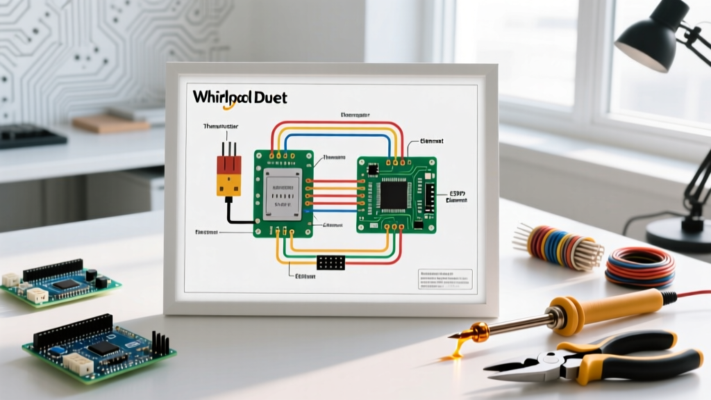
When a Whirlpool Duet dryer (common models include WED9270XW, WED8500BC, and YWED9450WW) tumbles but fails to produce heat, the immediate suspect is the heating element. However, blindly swapping parts without consulting the schematic is a costly mistake. As of 2026, professional diagnostic fees average $160 to $225, while the actual OEM replacement parts typically cost between $45 and $85. By learning to properly trace the wiring diagram for Whirlpool Duet dryer heating element circuits, you can isolate the exact point of failure using a standard digital multimeter.
The Duet series utilizes a sophisticated 240V split-phase electrical system paired with an electronic control board. Unlike older mechanical timer dryers, the Duet's heater circuit is governed by a network of thermal safety devices, solid-state relays, and a critical motor interlock switch. Understanding how voltage flows from the terminal block to the heating coil is the key to efficient troubleshooting.
The 240V Split-Phase Heater Circuit Explained
To troubleshoot effectively, you must understand how the wiring diagram maps the 240V supply. The power enters through the terminal block at the rear of the dryer, splitting into two 120V legs (L1 and L2) and a Neutral/Ground path. The heating element requires the full 240V across its terminals to generate adequate BTU output.
According to the schematic, L1 voltage is routed through the motor's centrifugal switch before it ever reaches the heater assembly. This is a vital safety feature: the heater will not receive power unless the drum is actively spinning. L2 voltage is routed through the electronic control board's heater relay, the operating thermostat, the high-limit thermostat, and the thermal cutoff before reaching the opposite terminal of the heating element. If any single component in this series circuit opens, the heater receives zero voltage.
Component Reference Matrix
Before opening the cabinet, familiarize yourself with the specific OEM part numbers and their expected electrical characteristics. Keep this matrix handy while testing.
| Component | OEM Part Number | Expected Multimeter Reading | Primary Failure Mode |
|---|---|---|---|
| Heating Element Assembly | WP8544771 | 10 to 15 Ohms | Coil breaks (Open) or shorts to metal housing |
| Thermal Cutoff Kit | WP279816 | 0 Ohms (Continuity) | Trips open at 250°F due to overheating |
| Operating Thermostat | WP3387134 | 0 Ohms (Room Temp) | Internal contacts weld shut or fail open |
| Thermal Fuse (Blower) | WP3392519 | 0 Ohms (Continuity) | Blows at 250°F due to restricted exhaust venting |
Step-by-Step Multimeter Troubleshooting
Follow this systematic approach to trace the circuit. You will need a digital multimeter and a 1/4-inch hex nut driver to remove the lower front access panel.
- Isolate Power and Access the Heater Box: Unplug the dryer or turn off the dedicated 30-amp double-pole breaker. Remove the three 1/4-inch hex screws securing the lower front kick panel. The heater assembly is located on the right side, housed in a metal duct.
- Test the Heating Element (WP8544771): Disconnect the two main wire harnesses from the element terminals. Set your multimeter to the 200Ω resistance setting. Place the probes on the two metal terminals. A healthy element will read between 10 and 15 ohms. If it reads 'OL' (Open Line), the internal coil is snapped, and the element must be replaced.
- Check for a Ground Fault: Leave one multimeter probe on an element terminal and touch the other probe to the bare metal casing of the heater box. The reading must be 'OL'. If you read any resistance, the element coil is sagging and shorting against the chassis, which will instantly trip your home's circuit breaker.
- Verify the Thermal Cutoff and High-Limit (WP279816): These are mounted directly on the heater housing. Disconnect the wires and test for continuity. They must read 0 ohms. Because the thermal cutoff is a one-time fuse, if it has blown, you must replace the entire kit and investigate why the dryer overheated.
- Test the Operating Thermostat (WP3387134): Located on the blower housing or the exit duct, this thermostat cycles the heat. At room temperature, it should show continuity (0 ohms). If it reads open, the control board will not send the L2 voltage signal to close the heater relay.
Edge Case: The Motor Centrifugal Switch Interlock
One of the most misunderstood aspects of the wiring diagram for Whirlpool Duet dryer heating element circuits is the motor switch interlock. Many DIYers test the heater, find it has perfect continuity, test the thermostats, find perfect continuity, and are left baffled as to why the element remains cold.
As shown in the schematic, the L1 leg of the 240V supply passes through the motor's centrifugal switch. This switch only closes when the motor reaches approximately 70% of its operating RPM. If the motor start capacitor is weak, the motor windings are degrading, or the switch contacts are clogged with conductive carbon dust from the motor brushes, the switch will fail to close. Consequently, the heater receives 0V on the L1 side. If your element and thermostats test perfectly, use the wiring diagram to locate the motor switch harness and test for 120V at the switch output while the drum is spinning.
Expert Insight: Never bypass the thermal fuse or thermal cutoff to test the dryer. According to the U.S. Consumer Product Safety Commission (CPSC), dryers are a leading cause of residential electrical fires. Bypassing these safety interlocks removes the only barrier between a clogged lint vent and an uncontrolled chassis fire. Always replace blown thermal devices with exact OEM equivalents.
Airflow Restrictions vs. Electrical Faults
The wiring diagram does not exist in a vacuum; it interacts directly with the dryer's physical airflow. If you replace a blown thermal cutoff (WP279816) or thermal fuse (WP3392519) and it blows again within three cycles, you do not have an electrical fault—you have an airflow fault.
When exhaust vents are crushed behind the dryer or clogged with lint, hot air stagnates in the heater box. The operating thermostat (WP3387134) fails to sense the cooling drop of incoming air, causing the heater to stay on continuously until the thermal cutoff trips at 250°F. The U.S. Department of Energy strongly recommends inspecting and cleaning the entire exhaust duct run to the exterior wall whenever a thermal safety device fails. Ensure you are using rigid metal ducting rather than flexible foil or plastic, which easily collapses and restricts airflow, violating National Electrical Code (NEC) and building safety standards for appliance venting.
Reassembly and Terminal Torque Specifications
Once the faulty component is identified and replaced, proper reassembly is critical. The wiring diagram shows multiple spade connectors and screw terminals. When reconnecting the main wires to the new heating element, ensure the female spade connectors are tight. If they are loose, they will slide on but create a high-resistance connection. Under a 22-amp load, a loose terminal will generate intense localized heat, melting the wire harness insulation and eventually causing an arc fault.
Use needle-nose pliers to gently crimp the spade connectors if they feel loose before sliding them onto the element tabs. When reattaching the main 240V power cord at the rear terminal block, torque the terminal screws firmly. A loose neutral or ground wire on a 4-prong NEMA 14-30R setup can cause erratic control board behavior and stray voltage on the dryer chassis. For comprehensive wiring schematics and tech sheets specific to your exact serial number, always consult the Whirlpool Official Support database before beginning any repair.
By combining a methodical reading of the wiring diagram with precise multimeter testing, you transform a frustrating appliance failure into a straightforward, cost-effective repair.