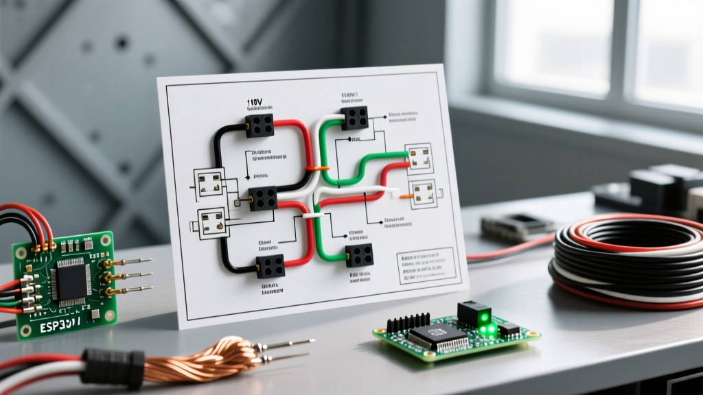

Decoding the Electric Motor Wiring Schematic: A Practical Walkthrough
Reading an electric motor wiring schematic can feel like deciphering an ancient language, especially when dealing with dual-voltage, single-phase induction motors. Whether you are retrofitting a vintage lathe, building a custom dust collection system, or wiring a heavy-duty air compressor, misunderstanding the schematic is the fastest way to burn out a $250 motor winding. In this 2026 guide, we bypass the theoretical fluff and walk through a real-world, step-by-step wiring scenario.
Our test subject for this walkthrough is the Leeson C6T17N58A (1 HP, 115/230V, 1800 RPM, single-phase capacitor-start motor), paired with a Dayton 2X442 Forward/Reverse Drum Switch. This exact combination remains an industry standard for DIY machining and light industrial applications due to its reliability and widespread availability, typically costing around $240 for the motor and $85 for the switch in the current market.
CRITICAL SAFETY WARNING: Before touching a single terminal, verify that the main breaker is locked out. According to OSHA's Lockout/Tagout (LOTO) standards, simply flipping a switch is insufficient; you must physically lock the disconnect and test for zero voltage with a CAT III rated multimeter.
Step 1: Understanding NEMA Lead Identification
Single-phase, dual-voltage motors typically feature eight or nine external leads (wires) emerging from the motor housing. These are standardized by the National Electrical Manufacturers Association (NEMA). As detailed in the NEMA MG 1 Motors and Generators standard, the leads are divided into run windings, start windings, and the centrifugal switch.
| Lead Label | Function | Description |
|---|---|---|
| T1, T2, T3, T4 | Run Windings | Provide the primary rotating magnetic field. T1/T2 is one coil, T3/T4 is the second. |
| T5, T8 | Start Windings | Provide the initial phase shift to start the motor. Reversing these relative to the run windings reverses motor direction. |
| T6, T7 | Centrifugal Switch | Disconnects the start winding once the motor reaches ~75% of rated RPM. |
| P1, P2 | Overload Protector | Thermal cutoff switch (often internal, but sometimes brought out as leads on specific models). |
Step 2: Configuring the Voltage Jumpers (115V vs. 230V)
Before wiring the external switch, you must configure the motor's internal terminal board for your facility's voltage. Running a 230V motor on a 115V supply will result in severe overheating, while applying 230V to a 115V configuration will instantly destroy the windings.
For 230V Operation (Recommended for 1HP+)
Operating at 230V cuts the amperage in half (7.4A vs 14.8A), reducing voltage drop and allowing for smaller wire gauges. As of the 2026 NEC cycle, 12 AWG THHN copper wire is the standard minimum for this 15A/20A circuit configuration, saving roughly 30% on copper material costs compared to the 10 AWG required for 115V.
- Run Windings in Series: Connect T2 to T3.
- Start Windings in Series: Connect T6 to T7 (if applicable to your specific schematic; on many modern Leeson models, the centrifugal switch is internally wired in series with the start winding, leaving only T5 and T8 exposed).
- Power Input Points: T1 and T4 become your main run winding inputs.
For 115V Operation
- Run Windings in Parallel: Connect T1 to T3, and T2 to T4.
- Start Windings in Parallel: Connect T5 to T6, and T7 to T8 (again, verify against your specific motor's printed schematic, as internal layouts vary by manufacturer).
- Power Input Points: The T1/T3 bundle and the T2/T4 bundle become your main inputs.
Step 3: Wiring the Drum Switch for Forward/Reverse
The core principle of reversing a single-phase induction motor is swapping the polarity of the start winding relative to the run winding. The Dayton 2X442 drum switch uses a 6-terminal block to achieve this safely without causing a dead short during the transition.
Terminal Mapping and Connections
Assuming the motor is configured for 230V, follow this exact wiring sequence:
- Power Supply L1 (Hot 1): Connect to Drum Switch Terminal 1.
- Power Supply L2 (Hot 2): Connect to Drum Switch Terminal 6.
- Motor Lead T1 (Run): Connect to Drum Switch Terminal 2.
- Motor Lead T4 (Run): Connect to Drum Switch Terminal 5.
- Motor Lead T5 (Start): Connect to Drum Switch Terminal 3.
- Motor Lead T8 (Start): Connect to Drum Switch Terminal 4.
- Internal Jumpers: Install a jumper wire from Terminal 1 to Terminal 3, and a second jumper from Terminal 4 to Terminal 6.
How it works: In the 'Forward' position, the switch routes L1 to T1/T5 and L2 to T4/T8. When you rotate the drum to 'Reverse', the mechanical cam swaps the start winding connections, routing L1 to T1/T8 and L2 to T4/T5. The run winding polarity remains static, but the start winding flips, reversing the magnetic field's initial push.
Step 4: Grounding and Enclosure Bonding
A common failure point in DIY motor wiring is neglecting the equipment grounding conductor (EGC). The green grounding screw on the motor housing must be bonded to the ground bus in your breaker panel using a continuous copper path. For a 230V, 1HP motor, use a minimum of 12 AWG bare or green-insulated copper wire. Never use the conduit as your sole ground path for motor circuits, as vibration can loosen locknuts over time, breaking the ground continuity.
Troubleshooting Common Schematic Wiring Failures
Even with a perfect schematic, physical wiring errors occur. According to Fluke's motor troubleshooting guidelines, over 40% of premature motor failures are linked to improper electrical connections. Here is how to diagnose the most frequent edge cases:
1. Motor Hums but Will Not Start
- The Cause: The start winding (T5/T8) is disconnected, or the centrifugal switch is stuck open.
- The Fix: Disconnect power. Use a multimeter to check continuity between T5 and T8. You should read a low resistance (typically 2 to 5 ohms). If it reads infinite (OL), the internal start winding is blown or the centrifugal switch contacts are fouled with dust.
2. Breaker Trips Instantly Upon Energizing
- The Cause: You have wired the run windings in parallel (115V configuration) but applied 230V power, OR you have shorted L1 to L2 inside the drum switch due to incorrect jumper placement.
- The Fix: Verify the T2-T3 series jumper for 230V operation. Re-verify the drum switch terminal mapping. A dead short across the lines will trip a 20A breaker in milliseconds.
3. Motor Runs in One Direction Only (Switch Does Nothing)
- The Cause: You accidentally swapped a start winding lead with a run winding lead (e.g., T5 is on the T1 terminal).
- The Fix: Identify the leads using a multimeter. Run windings (T1-T4) generally have a slightly lower resistance than start windings (T5-T8). Ensure the start winding is exclusively routed through the reversing contacts of the drum switch.
Final Commissioning Checklist
Before putting the motor under mechanical load, perform a dry run. Energize the circuit and observe the motor's amperage draw using a clamp meter. A 1HP Leeson motor running at 230V should draw approximately 7.4 Amps at full rated load, and roughly 2.5 to 3.5 Amps at no-load (freewheeling). If the no-load draw exceeds 5 Amps, you have a binding mechanical issue, incorrect voltage jumpers, or a failing bearing. Always allow the motor to come to a complete stop before throwing the drum switch from Forward to Reverse; 'plugging' (reversing while at full speed) generates massive current spikes that can weld the drum switch contacts shut.