
The Definitive Wiring Diagram for a Single Pole Switch: Code Topologies
When electrical professionals and advanced DIYers reference a wiring diagram for a single pole switch, they are typically navigating one of two fundamental circuit topologies: Power at the Switch or Power at the Light (switch loop). Understanding the distinction is not just a matter of making the light turn on; it is the foundation of National Electrical Code (NEC) compliance and fire prevention. According to the U.S. Consumer Product Safety Commission (CPSC), electrical distribution and lighting equipment are consistently among the top causes of residential fires, often stemming from improper terminations and outdated wiring methods.
Before stripping a single wire, you must identify your topology. A standard single-pole switch (such as the ubiquitous Leviton Decora 5601 15A switch) has two brass terminal screws for the hot conductors and one green screw for the equipment grounding conductor. It does not have a silver terminal for a neutral wire, yet modern code strictly dictates how the neutral must be handled within the switch box.
Topology 1: Power at the Switch Box
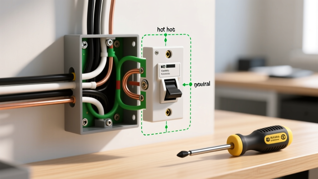
In this scenario, the main feed cable (e.g., 14/2 or 12/2 NM-B) enters the switch box first. The black (hot) wire connects directly to one of the brass screws on the single-pole switch. The white (neutral) wire from the feed is spliced directly to the white (neutral) wire of the cable heading up to the light fixture. The black wire of the fixture cable connects to the second brass screw on the switch, acting as the switched hot (load). All bare copper ground wires are spliced together and pigtailed to the switch's green grounding screw and the metal box (if applicable).
Topology 2: Power at the Light (Switch Loop)
Here, the power enters the ceiling fixture box first. A 2-conductor cable drops down to the switch. Historically, the white wire in this drop was used as a hot feed and the black as the switched return. However, NEC Article 200.7(C)(2) requires that if a white wire is used as a hot (ungrounded) conductor in a switch loop, it must be permanently re-identified with black tape or paint at both ends. More critically, modern code has fundamentally altered this diagram.
The NEC 404.2(C) Mandate: The Neutral at the Switch
The most common code violation in older single-pole switch diagrams is the omission of a neutral wire at the switch box. To accommodate smart switches, occupancy sensors, and LED dimmers (like the Lutron Maestro MACL-153M) that require a continuous low-current path to operate their internal electronics, NEC 404.2(C) now mandates that a grounded circuit conductor (neutral) must be present at virtually all switch locations controlling lighting loads.
Code Compliance Alert: If you are running a new switch loop in 2026, you must use 3-conductor cable (e.g., 14/3 or 12/3 NM-B) between the light and the switch, even if the single-pole switch itself only uses two wires. The white neutral wire must be capped in the back of the switch box with a WAGO 221 lever-nut or wire nut, ready for future smart-device upgrades.
Conductor Sizing, Box Fill, and Termination Matrix
Proper wire gauge selection and box volume calculations are non-negotiable for safety. Overcrowding a switch box causes heat buildup, which degrades wire insulation and leads to arc faults. The following matrix outlines the strict parameters based on NEC Article 314.16 for standard residential single-pole switch installations.
| Parameter | 15-Ampere Circuit | 20-Ampere Circuit |
|---|---|---|
| Wire Gauge (NM-B) | 14 AWG Solid Copper | 12 AWG Solid Copper |
| Breaker Size | 15A (AFCI/GFCI as required) | 20A (AFCI/GFCI as required) |
| NEC Box Fill Allowance per Conductor | 2.0 Cubic Inches | 2.25 Cubic Inches |
| Minimum Single-Gang Box Volume | 18 Cu. In. (Standard deep box) | 22.5 Cu. In. (Extra deep box) |
| Wire Strip Length | 5/8 Inch (Exact) | 5/8 Inch to 3/4 Inch |
| Terminal Torque Specification | 12 to 14 in-lbs | 16 to 18 in-lbs |
Calculating Box Fill (NEC 314.16(B))
To ensure your box is legally sized, count the conductors. For a standard 'Power at the Switch' setup with one feed and one load cable (14 AWG):
- 4 current-carrying conductors (2 hots, 2 neutrals) = 8.0 cu in.
- 1 Equipment Ground (counts as 1 regardless of how many grounds enter) = 2.0 cu in.
- 1 Switch Device (counts as 2 conductors) = 4.0 cu in.
- Internal Cable Clamps (counts as 1) = 2.0 cu in.
- Total Required Volume: 16.0 Cubic Inches. A standard 18 cu. in. deep single-gang box is compliant.
Step-by-Step Code-Compliant Installation Flow
Follow this exact sequence to ensure a safe, inspection-ready installation. You will need a calibrated torque screwdriver (such as the CDI 401SM) and a precision wire stripper (like the Klein Tools 11063W).
- De-energize and Verify: Turn off the breaker. Use a non-contact voltage tester (NCVT) and a digital multimeter to verify 0V between the hot, neutral, and ground wires. Never rely solely on an NCVT.
- Prepare Conductors: Strip exactly 5/8 inch of insulation. Do not nick the copper conductor; a nick creates a micro-fracture that will snap under thermal expansion cycles.
- Grounding First (NEC 250.148): Connect all bare copper grounds using a copper crimp or wire nut. Run a 6-inch 14 AWG bare copper pigtail to the green grounding screw on the switch. If using a metal box, the box must also be bonded to the ground splice.
- Neutral Splice: Connect the white neutral wires together. Cap them securely and push them to the very back of the box to reserve space for the hot wires.
- Terminate Hot Conductors (Side-Wiring Only): Form a clockwise 'J-hook' with the stripped black wires. Hook them around the brass terminal screws so that tightening the screw pulls the wire inward. Do not use the push-in 'backstab' holes. Backstab connections rely on a tiny spring-metal wedge that loosens over time due to thermal cycling, leading to high-resistance arcing and fires.
- Apply Torque: Tighten the brass terminal screws to exactly 14 in-lbs (for 14 AWG) using a torque screwdriver. This prevents under-tightening (which causes arcing) and over-tightening (which strips the brass threads or snaps the screw).
- Secure and Fold: Gently fold the wires in an accordion pattern. Mount the switch using the provided #6-32 mounting screws, ensuring the device yoke sits flush against the drywall or plaster ear to prevent the faceplate from cracking.
Troubleshooting Common Single-Pole Failures
Even with a perfect wiring diagram for a single pole switch, field conditions can introduce anomalies. Here is how to diagnose edge cases based on OSHA electrical safety troubleshooting standards:
Ghost Voltage and LED Flickering
If you install a low-wattage LED bulb and it flickers or glows faintly when the single-pole switch is OFF, you are likely experiencing capacitive coupling (ghost voltage). This happens when the switched hot wire runs parallel to a constantly hot wire in the same cable or conduit for long distances (over 50 feet). The Fix: Install an LED-compatible dummy load resistor (like the Lutron LUT-MLC) in parallel with the light fixture at the ceiling box, or upgrade to a higher-quality LED driver with built-in suppression.
Voltage Drop on Long Switch Loops
If the light is located 100 feet away from the panel, and the switch is 50 feet beyond the light, you have 150 feet of total conductor length on a 14 AWG circuit. Under a heavy load, this causes voltage drop, resulting in dim lights and premature ballast failure. The Fix: Upsize the entire circuit to 12 AWG wire and use a 20A breaker, or relocate the switch closer to the panel to minimize the unswitched hot run.
Final Safety and Inspection Notes
As of the latest NFPA 70 (National Electrical Code) updates, AFCI (Arc-Fault Circuit Interrupter) protection is required for virtually all 15A and 20A 120V branch circuits supplying outlets and switches in dwelling units. Ensure your single-pole switch circuit originates from a properly functioning AFCI breaker or an AFCI receptacle upstream. A correctly wired single-pole switch should never cause nuisance AFCI trips; if it does, inspect the neutral splices for loose connections or shared neutrals between adjacent circuits, which are the primary culprits of arc-fault nuisance tripping.