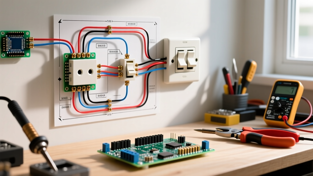

The Anatomy of Multi-Location Control
Controlling a single lighting load from three or more locations requires a precise sequence of switches. Unlike a standard single-pole setup, a four-way circuit relies on two 3-way switches acting as the 'bookends' of the circuit, with one or more 4-way switches positioned in the middle. When a multi-location lighting circuit fails, interpreting the wiring diagram for a four way switch is your most critical diagnostic step. Misunderstanding the traveler wire routing or the internal toggle mechanics of the 4-way switch leads to hours of frustrating, trial-and-error troubleshooting.
In this guide, we break down the exact signal paths, provide a diagnostic matrix for common failure modes, and outline a professional multimeter testing protocol to isolate faults in 2026's modern LED-integrated lighting environments.
Decoding the Wiring Diagram for a Four Way Switch
Before touching a screwdriver, you must visualize the schematic. A standard 4-way switch (such as the widely used Leviton Decora 5604-2W) does not have a 'Line' or 'Load' terminal. Instead, it features two pairs of traveler terminals.
Signal Path Tracing
- Node 1 (Power Source): 120V AC enters the first 3-way switch's common (black) terminal.
- Node 2 (First Traveler Set): Power exits via one of the brass traveler terminals, traveling through a 3-wire cable (typically black, red, white) to the 4-way switch's 'Input' pair.
- Node 3 (The 4-Way Cross): Internally, the 4-way switch either passes the current straight through (parallel) or crosses it (X-pattern) to the 'Output' pair.
- Node 4 (Second Traveler Set): The current travels to the second 3-way switch's brass traveler terminals.
Node 5 (The Load): If the second 3-way switch's internal wiper aligns with the energized traveler, power flows out the common terminal to the light fixture.
Expert Insight: The most common wiring error occurs when an electrician or DIYer mistakenly lands the neutral (white) wire on a traveler terminal instead of pigtailing it directly to the load. A wiring diagram for a four way switch will always show the neutral bypassing all switch terminals entirely.
Diagnostic Matrix: Symptoms vs. Wiring Faults
Use this matrix to narrow down your troubleshooting focus based on the exact behavior of the lighting circuit.
| Circuit Symptom | Probable Fault Location | Diagram Node to Inspect |
|---|---|---|
| Light works from only one 3-way switch; 4-way does nothing. | Traveler wire disconnected or broken between 3-way and 4-way. | Node 2 or Node 4 (Traveler pairs) |
| Light works from 3-ways, but toggling 4-way turns it OFF permanently. | 4-way switch wired in series with the load, or travelers miswired to common. | Node 3 (4-Way Input/Output pairs) |
| Breaker trips instantly when toggling the 4-way switch. | Dead short between travelers and ground, or neutral landed on traveler terminal. | Node 3 & Grounding Bus |
| LED fixture flickers or glows faintly when OFF. | Capacitive coupling on long traveler runs or ghost voltage from smart switches. | Node 2 & Node 4 (Long cable runs) |
Step-by-Step Multimeter Troubleshooting Protocol
To safely and accurately diagnose the circuit, you need a True-RMS multimeter rated for CAT III environments, such as the Fluke 117 (approx. $180). According to Fluke's safety guidelines on measurement categories, CAT III is mandatory for testing hardwired lighting circuits and distribution panels.
- Isolate and Verify: Turn off the breaker. Use a non-contact voltage tester (NCVT) to confirm the absence of voltage at the first 3-way switch. Always test the NCVT on a known live source before and after use.
- Disconnect and Label: Remove the 4-way switch from the wall box. Label the two wires from the first 3-wire cable as 'Set A' and the two wires from the second 3-wire cable as 'Set B'. Disconnect all four traveler wires from the switch terminals.
- Continuity Testing the Switch: Set your multimeter to continuity (the diode/beep symbol). Place probes on Set A's terminals. Toggle the switch. The meter should beep on one pair of diagonal terminals (e.g., Top-Left to Bottom-Right), and then switch to the other diagonal pair (Top-Right to Bottom-Left) when flipped. If the switch shows continuity straight across (Top-Left to Top-Right) regardless of toggle position, the internal mechanical wiper is fused or broken. Replace the switch.
- Traveler Integrity Check: With the power still OFF, go to the first 3-way switch. Disconnect the travelers. Place one multimeter probe on a traveler wire at the 3-way box, and the other probe on the corresponding wire at the 4-way box. You should read less than 1.0 ohm of resistance. An 'OL' (Open Loop) reading indicates a severed wire inside the wall, often caused by a drywall screw or a failed backstab connection.
- Voltage Drop Test (Live): If continuity checks pass but the circuit still fails, restore power. Set the multimeter to AC Voltage. Measure between the energized traveler at the 4-way box and the bare copper ground. You should read a stable 120V (±5%). A reading of 40V-90V indicates a high-resistance fault, usually a loose wire nut or a degraded backstabbed terminal upstream.
Hardware Specifications and Box Fill Requirements
When replacing components or upgrading to heavier-duty commercial switches, you must adhere to strict physical and electrical codes. The NFPA 70 (National Electrical Code) dictates precise box fill calculations to prevent overheating and wire crushing.
- Switch Selection: For standard residential 15A circuits, the Leviton 5604-2W Decora 4-Way ($14.50) is the industry standard. For commercial 20A circuits, upgrade to the Leviton 5240-W 20A Toggle ($18.25), which features heavier brass contacts and side-wiring clamps.
- Wire Gauge Constraints: 14 AWG copper is limited to 15A breakers (NEC 240.4(D)). If your circuit is on a 20A breaker, you must use 12 AWG wire and switches specifically rated for 20A. Never mix 14 AWG wire on a 20A breaker.
- Box Fill Calculation: A 4-way switch box contains four current-carrying traveler wires, one equipment grounding conductor, and the switch yoke itself. According to NEC 314.16, for 14 AWG wire (2.0 cubic inches per conductor), the calculation is: 4 travelers + 1 ground + 2 (for the device yoke) = 7 allowances. 7 x 2.0 = 14.0 cubic inches minimum box volume. If you are adding pigtails, the volume requirement increases. Use a deep 2-gang or 4-square box with a mud ring to ensure adequate heat dissipation.
Edge Cases: Ghost Voltages and LED Flicker
In 2026, the transition to ultra-low-wattage LED lighting has introduced a massive headache for 4-way switch troubleshooting: ghost voltage flicker. When traveler wires run parallel inside a wall cavity for more than 50 feet, capacitive coupling can induce a 'phantom' voltage (often 30V to 60V) on the unenergized traveler wire.
While this phantom voltage lacks the amperage to shock you or illuminate an incandescent bulb, modern LED drivers are so sensitive that this trapped capacitance slowly charges the internal capacitor, causing the bulb to strobe or flash every few seconds when the switches are in the OFF position.
The Fix: Bleeder Resistors
If your wiring diagram checks out perfectly and all switches test functional, but your LED load is flickering, you do not have a wiring fault—you have a capacitance issue. Install a Lutron LUT-MLC (approx. $25) or a generic 100k-ohm, 1/2-watt bleeder resistor across the Line and Load wires at the light fixture itself. This provides a high-impedance path to drain the capacitive coupling, instantly resolving the flicker without altering the switch wiring.
Safety and Final Verification
Working with multi-way switching circuits requires meticulous attention to grounding. Ensure all bare copper and green grounding wires are pigtailed together and bonded to the metal switch box (if applicable) and the green ground screw on every switch. The U.S. Consumer Product Safety Commission (CPSC) emphasizes that improper grounding in multi-switch setups is a leading cause of residential electrical shocks, particularly when a hot traveler wire accidentally contacts the metal yoke or wall box.
By methodically tracing the wiring diagram for a four way switch, utilizing a CAT III multimeter, and understanding the modern edge cases of LED capacitance, you can diagnose and resolve virtually any multi-location lighting fault with professional precision.


