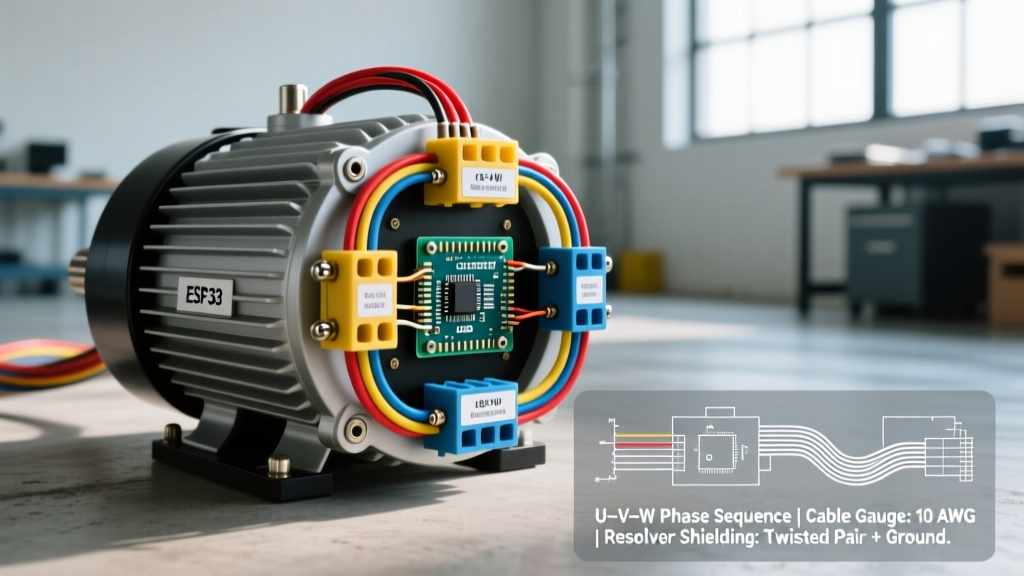

Why 3-Phase AC Motors Dominate Custom EV Builds
When engineering a high-performance electric vehicle (EV) conversion—whether retrofitting a classic 1970s pickup or building an off-road electric buggy—selecting the right powertrain is only half the battle. The true reliability of your build hinges on flawless 3 phase electric motor wiring. Unlike legacy DC series motors that rely on simple brush contactors, modern 3-phase AC induction and permanent magnet synchronous motors (PMSM) require sophisticated inverter integration, high-voltage DC bus management, and meticulous electromagnetic interference (EMI) shielding.
As of 2026, the shift toward 400V and 800V architectures in the commercial EV sector has trickled down to the enthusiast market. However, the majority of light-truck and classic car conversions still operate in the 96V to 144V nominal range (peaking around 400V under specific high-power configurations). Understanding how to properly route, crimp, and shield the U, V, and W phase cables is the difference between a smooth, regenerative-capable drivetrain and a catastrophic inverter failure.
System Architecture: Netgain Hyper9 and Curtis 1238E
To provide actionable, real-world guidance, this guide focuses on one of the most popular and robust setups in the 2026 EV conversion market: the Netgain Hyper9 3-phase AC motor paired with the Curtis 1238E inverter/controller. This combination retails between $4,800 and $5,500 and is the gold standard for vehicles requiring up to 100kW of peak power and 240 Nm of torque.
DC Series vs. 3-Phase AC Architecture
- DC Series Motors: Require heavy contactors, lack native regenerative braking, and suffer from brush wear. Wiring is relatively simple but inefficient.
- 3-Phase AC Motors: Utilize an inverter to convert DC battery power into high-frequency AC waveforms. They offer superior torque density, zero brush maintenance, and full regenerative braking capabilities, but demand strict adherence to high-voltage wiring protocols and sensor shielding.
Cable Selection and Insulation Standards
Wiring a 3-phase motor in a vehicular environment subjects the cables to extreme vibration, thermal cycling, and potential chemical exposure. Standard automotive primary wire is entirely inadequate for the high-voltage DC bus or the high-frequency AC phase lines.
For the DC High-Voltage Bus (Battery to Inverter), you must use 2/0 AWG or 4/0 AWG copper welding cable with Class K stranding. Class K features ultra-fine copper strands that resist fatigue from engine bay vibrations. Insulation must be rated for at least 600V (1000V preferred) and feature a silicone or EPDM (Ethylene Propylene Diene Monomer) jacket to withstand under-hood temperatures exceeding 125°C.
For the AC Phase Cables (U, V, W) running from the inverter to the motor, 2/0 AWG flexible silicone cable is standard. Because the Curtis 1238E utilizes Pulse Width Modulation (PWM) switching frequencies up to 16 kHz, the skin effect can cause high-frequency currents to travel on the outer edge of the conductor. Using highly stranded, fine-wire silicone cables mitigates excessive heating.
Step-by-Step 3 Phase Electric Motor Wiring Procedure
1. DC Bus Integration and Pre-Charge Circuit
Before connecting the 3-phase motor, the DC bus must be safely energized. The Curtis 1238E inverter contains large electrolytic capacitors. If you connect a 144V battery pack directly to the inverter via a main contactor, the inrush current will instantly weld the contactor contacts and potentially destroy the inverter's internal bus bars.
The Solution: You must wire a pre-charge circuit. This involves a secondary, smaller contactor and a high-wattage ceramic resistor (typically a 50W, 1kΩ resistor). When the ignition is turned on, the pre-charge contactor closes first, slowly charging the capacitors through the resistor over 500 to 800 milliseconds. Once the bus voltage reaches 90% of the pack voltage, the main contactor closes, and the pre-charge circuit disengages.
2. Routing the U, V, and W Phase Cables
The 3 phase electric motor wiring connects the inverter's output terminals (U, V, W) to the motor's corresponding stator terminals.
Expert Tip: Does phase sequence matter? In a 3-phase AC system, swapping any two phase cables (e.g., swapping U and V) will reverse the motor's direction of rotation. While you can physically swap the cables to reverse direction, best practice in 2026 is to wire them sequentially (U-to-U, V-to-V, W-to-W) and use the Curtis 1313 handheld programmer to reverse the direction in software. This keeps physical wiring standardized for future diagnostics.
Use a hydraulic crimper (such as the Greenlee EK425LX) with the correct hexagonal die for your 2/0 AWG lugs. Never use a hammer crimper for high-voltage EV applications; improper compression leads to micro-arcing and thermal runaway under heavy acceleration loads. Terminate all connections with dual-wall, adhesive-lined heat shrink to prevent moisture ingress and corrosion.
3. Resolver and Sensor Shielding (The EMI Trap)
The most common point of failure in 3-phase EV conversions is not the high-voltage power cables, but the low-voltage sensor wiring. The Hyper9 motor uses a resolver to communicate the exact rotor position back to the Curtis inverter. The inverter uses this data to time the PWM sine waves perfectly.
Because the inverter switches hundreds of amps at 16 kHz, it generates massive electromagnetic interference (EMI). If your resolver cable is unshielded or routed parallel to the U, V, and W phase cables, the EMI will induce phantom voltages in the signal wires. The inverter will misread the rotor position, resulting in severe stuttering, torque cutouts, or an immediate 'Phase Fault' shutdown.
Actionable Fix: Use a 6-pin or 12-pin Shielded Twisted Pair (STP) cable for the resolver. Ground the shield drain wire only at the inverter end (single-point grounding) to prevent ground loops. Maintain at least a 4-inch physical separation between the high-voltage AC phase cables and the low-voltage sensor harness.
Wire Gauge & Torque Specifications Matrix
| Connection Point | Recommended Wire Gauge | Lug Type | Hardware Size | Torque Specification |
|---|---|---|---|---|
| Battery to Main Contactor | 4/0 AWG Class K | Heavy Duty Copper (3/8" hole) | 3/8"-16 Stainless Steel | 25 ft-lbs (34 Nm) |
| Inverter DC Input (B+ / B-) | 2/0 AWG Silicone | Standard Copper (5/16" hole) | 5/16"-18 Zinc Plated | 18 ft-lbs (24 Nm) |
| Inverter to Motor (U, V, W) | 2/0 AWG Silicone | Standard Copper (M10 hole) | M10x1.5 Metric Flange | 22 ft-lbs (30 Nm) |
| Motor Terminal Box (Stator) | 2/0 AWG Silicone | Standard Copper (M10 hole) | M10x1.5 Metric Flange | 22 ft-lbs (30 Nm) |
Real-World Failure Modes and Edge Cases
Even with perfect 3 phase electric motor wiring, vehicular environments introduce unique mechanical and electrical stressors. Here are the edge cases you must engineer against:
- VFD-Induced Bearing Fluting: The high-frequency PWM signals from the inverter can induce common-mode voltages on the motor shaft. If this voltage arcs through the motor bearings to the chassis, it causes microscopic pitting (fluting), leading to catastrophic bearing failure within 10,000 miles. Solution: Install an AEGIS shaft grounding ring on the drive end of the motor to provide a safe path to ground.
- Thermal Derating from Poor Crimps: A 2/0 AWG cable crimped with the wrong die will exhibit higher electrical resistance. At 300 amps of continuous draw (e.g., climbing a steep grade), a poor crimp will generate localized heat, melting the insulation and triggering the inverter's thermal protection limp-mode.
- Chassis Ground Faults: Unlike 12V systems, the high-voltage DC bus in an EV is completely isolated from the vehicle chassis. If a phase cable chafes against the frame, the inverter will detect an isolation fault and instantly shut down. Always use split-loom conduit and P-clamps with rubber cushions when routing cables through the firewall or along the frame rails.
Industry Standards and References
When designing and executing high-voltage EV wiring, adherence to established safety and engineering standards is non-negotiable. For comprehensive guidelines on electric vehicle powertrain safety and electrical codes, refer to the following authoritative resources:
- U.S. Department of Energy: Electric Vehicles Basics - Provides foundational data on EV powertrain architectures, battery safety, and high-voltage system integration.
- NFPA 70: National Electrical Code (NEC) - While primarily for stationary installations, Article 625 of the NEC outlines critical safety standards for EV charging and high-voltage DC isolation that inform safe conversion practices.
- National Renewable Energy Laboratory (NREL): Transportation Research - Offers in-depth technical papers on inverter switching frequencies, EMI mitigation, and 3-phase motor efficiency mapping.
By respecting the physics of 3-phase power and treating EMI management as a priority equal to cable sizing, your EV conversion will deliver reliable, gas-torch torque for years to come.