
The Breaker Panel Connection: Sizing and Wire Gauge
Before examining the internal wiring diagram for electric water heater thermostat components, the circuit origin at the main breaker panel must be correctly configured. Electric storage water heaters (typically 40 to 50 gallons) utilize dual 4500-watt heating elements operating on 240 volts. According to the National Electrical Code (NEC) Article 422.13, storage-type water heaters of 120 gallons or less are classified as continuous loads. This mandates that the branch circuit be rated at no less than 125% of the appliance's nameplate rating.
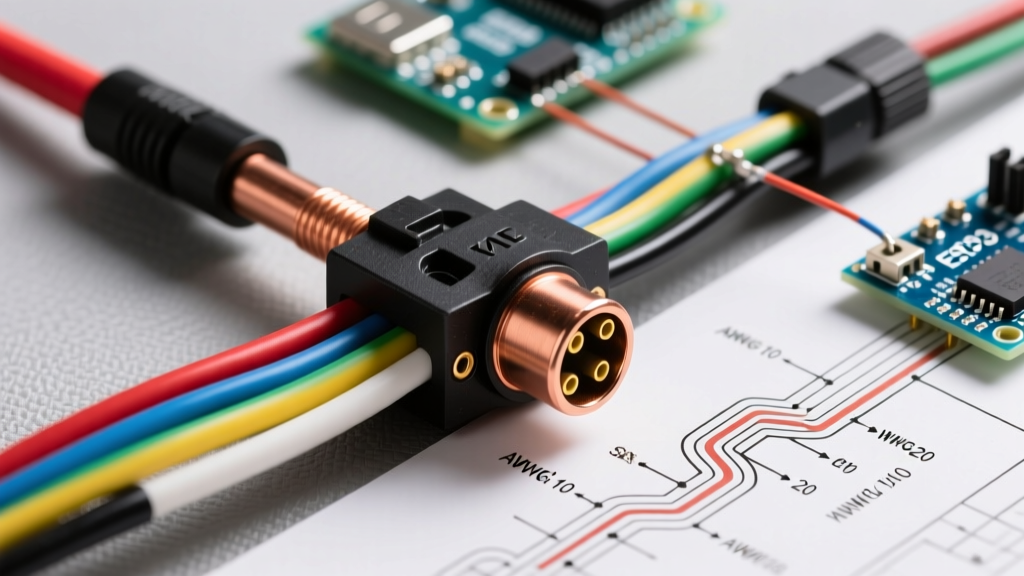
For a standard 4500W element at 240V, the base amperage is 18.75 amps. Multiplying by 1.25 yields a minimum circuit requirement of 23.43 amps. While a 25-amp double-pole breaker technically satisfies this mathematical threshold, the universal industry standard—and the requirement for most manufacturer warranties—is a 30-amp double-pole breaker paired with 10 AWG copper wire (typically 10/2 NM-B with a bare ground).
2026 NEC & Material Note: With copper prices stabilizing around $1.65 per linear foot for 10/2 NM-B in early 2026, some DIYers attempt to save money by using 8 AWG aluminum wire. While permissible if the breaker terminals are rated for AL/CU, the voltage drop over runs exceeding 80 feet necessitates upsizing to 6 AWG aluminum. Always verify the terminal torque specifications on your specific panel (e.g., Square D HOM230CP requires 35 in-lbs for 10 AWG copper).
Understanding Dual-Element Thermostat Logic
Most residential electric water heaters (such as the Rheem PROE50 or Bradford White RE350T6) utilize a non-simultaneous operation logic. This means the upper and lower elements will never draw power at the exact same time, preventing the 30-amp breaker from tripping under a combined 37.5-amp load.
- The Upper Thermostat (Master): Monitors the top third of the tank. When the top water is cold, it routes 240V to the upper element and cuts power to the lower thermostat.
- The Lower Thermostat (Slave): Only receives power once the upper thermostat is satisfied and switches the circuit downstream. It maintains the baseline temperature of the lower tank volume.
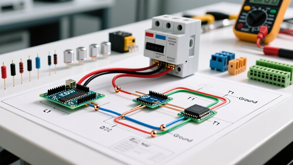
Step-by-Step Wiring Diagram for Electric Water Heater Thermostat
Follow this precise routing sequence for a standard non-simultaneous setup using a Honeywell/Robertshaw-style replacement thermostat kit (e.g., SP112670 Upper / SP112671 Lower).
1. Grounding the Chassis
Never route the equipment grounding conductor through the thermostats. Connect the bare copper ground wire from your 10/2 NM-B cable directly to the green grounding screw located on the upper thermostat mounting bracket or the dedicated ground bus on the tank's exterior junction box. Torque to 20 in-lbs.
2. Upper Thermostat Wiring
- Route the Black (Line 1) wire from the junction box to the L1 terminal on the upper thermostat.
- Route the White wire (re-identified with black electrical tape) to the L3 terminal on the upper thermostat.
- Connect the upper heating element's left screw to the upper thermostat's H1 (or T2) load terminal.
- Connect the upper heating element's right screw to the upper thermostat's H2 (or T4) load terminal.
- Run a jumper wire (usually included, often red or black 14 AWG) from the upper thermostat's T2 transfer terminal down to the lower thermostat's L1 terminal.
- Run a second jumper wire from the upper thermostat's T4 transfer terminal down to the lower thermostat's L3 terminal.
3. Lower Thermostat Wiring
- Verify the jumper wires from the upper T2 and T4 are securely fastened to the lower L1 and L3 line terminals.
- Connect the lower heating element's left screw to the lower thermostat's H1 load terminal.
- Connect the lower heating element's right screw to the lower thermostat's H2 load terminal.
Breaker & Wire Gauge Sizing Matrix
Use the following matrix to ensure your panel breaker and wire gauge match your specific water heater nameplate. This data aligns with NFPA 70 (NEC) standards for continuous appliance loads.
| Element Wattage | Voltage | Base Amps | 125% Continuous Load | Min. Wire Gauge (Copper) | Standard Breaker Size |
|---|---|---|---|---|---|
| 3000W | 240V | 12.5A | 15.6A | 12 AWG | 20A Double-Pole |
| 3800W | 240V | 15.8A | 19.7A | 12 AWG | 20A or 25A Double-Pole |
| 4500W | 240V | 18.75A | 23.4A | 10 AWG | 30A Double-Pole |
| 5500W | 240V | 22.9A | 28.6A | 8 AWG | 30A or 35A Double-Pole |
Common Failure Modes & Multimeter Troubleshooting
When a water heater fails to produce hot water, the issue is rarely the breaker panel unless the breaker has physically tripped or the bus bar is damaged. According to the U.S. Department of Energy, sediment buildup and thermostat failure are the primary culprits. Always follow OSHA Lockout/Tagout procedures by shutting off the 30A breaker and verifying zero voltage before touching terminals.
Testing the Heating Elements
Disconnect the power and remove the wires from the element terminals. Set your multimeter to Ohms (Ω). Place one probe on each element screw terminal.
- 4500W Element: Should read between 12.0 Ω and 13.0 Ω.
- 3800W Element: Should read between 14.5 Ω and 15.5 Ω.
- Infinite (OL): The internal element coil is broken. Replace the element.
- Zero (0.0 Ω): The element is shorted internally. Replace immediately.
Ground Fault Test: Set the meter to the highest Ohm range (e.g., 20MΩ). Place one probe on an element screw and the other on the bare steel tank. Any reading other than "OL" (infinite) means the element casing has ruptured and is leaking current to the tank. This is a severe shock hazard and requires immediate element replacement.
The "Hidden" High-Limit Reset Trip (ECO)
The upper thermostat houses an Energy Cut-Off (ECO) switch. If the upper thermostat's internal contacts weld shut due to arcing (common in hard-water areas where elements cycle rapidly), the water temperature will exceed safe limits. The ECO is a bimetallic snap-disc switch designed to trip at 150°F to 180°F, physically breaking the 240V line before the water flashes to steam and ruptures the tank.
If you press the red "Reset" button on the upper thermostat and it clicks, but trips again within 48 hours, do not keep resetting it. The upper thermostat contacts are permanently welded. You must replace both the upper and lower thermostats, as the lower thermostat may have also degraded from running at excessive temperatures during the runaway event.
FAQ: Panel and Thermostat Wiring Questions
Can I use a 40-amp breaker for a 4500W water heater?
No. While a 40-amp breaker will not immediately trip, it violates NEC overcurrent protection rules. If a short circuit occurs in the 10 AWG wire, the wire insulation will melt and catch fire before the 40-amp breaker registers the fault. The breaker must match the wire's ampacity (30A for 10 AWG copper).
Why is my white wire connected to a brass screw?
In a 240V appliance circuit, there is no neutral wire. The white wire in your 10/2 cable acts as a second hot leg. The NEC requires you to re-identify this white wire with black or red electrical tape at both the panel and the water heater junction box to indicate it is an ungrounded (hot) conductor carrying 120V relative to ground.