
Introduction to Western Plow Electrical Architecture
Installing or troubleshooting a snowplow electrical system requires a precise understanding of high-current DC dynamics and low-voltage signal routing. When consulting a wiring diagram for Western plow setups—whether for the legacy Ultramount, the MVP3, or the Wide-Out push-frame systems—technicians must navigate a complex intersection of hydraulic pump power circuits, lighting harnesses, and cabin control modules. In 2026, the shift toward Multiplex (MPC) architectures has simplified physical wiring but increased the demand for strict adherence to wire gauge specifications and pinout color codes.
This comprehensive reference guide breaks down the exact American Wire Gauge (AWG) requirements, standard color code matrices, and real-world failure modes associated with Western snowplow harnesses. Whether you are replacing a corroded 13-pin lighting connector or upgrading the main battery cables to prevent solenoid chatter, this guide provides the actionable data you need.
Decoding the Wiring Diagram for Western Plow Harnesses
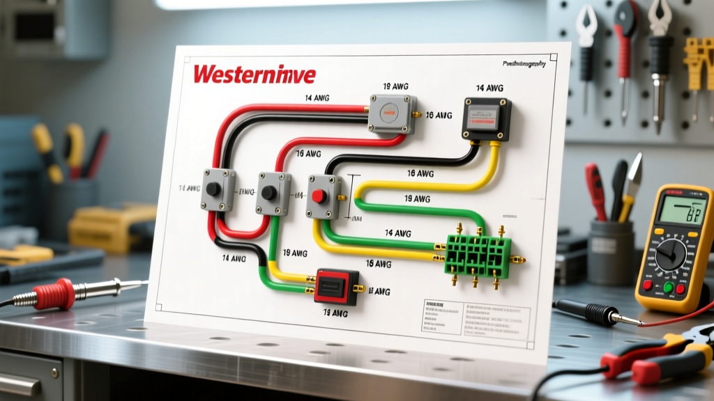
Western plow wiring diagrams generally divide the electrical system into three distinct sub-circuits:
- Main Power and Ground (Hydraulic Pump): High-amperage circuits responsible for actuating the hydraulic gear pump.
- Lighting and Markers: Low-amperage circuits that mirror and extend the truck’s OEM lighting to the plow blade.
- Control and Multiplex Signals: Low-voltage data and trigger wires connecting the in-cab joystick/controller to the under-hood solenoids and Multiplex Control (MPC) modules.
Historically, Western utilized a '3-plug' system (separate plugs for power, lights, and control). Modern systems, particularly on the MVP3 and Ultramount 2, frequently consolidate these into a Multiplex system utilizing a single 13-pin or 7-pin combined connector, alongside the heavy-gauge power lugs. You can verify your specific schematic via the Western Plows official literature portal, but the foundational wire gauge and color principles remain consistent across platforms.
Critical Wire Gauge (AWG) Specifications
The most common point of failure in aftermarket snowplow installations is voltage drop caused by undersized main power cables. The hydraulic pump motor on a Western plow can draw between 120A and 180A under continuous load, with inrush currents exceeding 220A when the solenoid first engages against cold, viscous hydraulic fluid.
According to standard AWG ampacity charts and SAE J1128 standards for automotive primary cable, selecting the correct gauge is non-negotiable.
| Circuit Application | Recommended AWG | Max Amperage | Fusing Requirement | Insulation Type |
|---|---|---|---|---|
| Main Battery Positive (Pump) | 2 AWG (or 1/0 AWG for runs >12ft) | 200A+ | 150A MAXI or Mega Fuse | SGT / Welding Cable |
| Main Chassis Ground | 2 AWG | 200A+ | None (Direct to frame/battery) | SGT / Welding Cable |
| Lighting Harness (13-Pin) | 14 AWG to 16 AWG | 15A per circuit | 15A Mini/ATO Fuses | GXL / TXL Cross-linked |
| Control / Multiplex Signals | 18 AWG | 3A - 5A | Protected via MPC Module | GXL / TXL |
| Solenoid Trigger Wire | 14 AWG | 10A | 10A Inline Fuse | GXL |
The Voltage Drop Nuance
Many installers default to 4 AWG wire for the main power run to save money and ease routing through the firewall or grille. This is a critical error. Let's calculate the voltage drop for a 10-foot physical run (20 feet of total wire including positive and ground) using 4 AWG wire carrying 150A. The resistance of 4 AWG is roughly 0.248 ohms per 1,000 feet.
Voltage Drop Calculation:
VD = (2 × Length × Current × Resistance per 1000ft) / 1000
VD = (20 × 150 × 0.248) / 1000 = 0.744 VoltsWhile 0.744V seems small, it represents a 6.2% drop on a 12V system. SAE and NEC guidelines recommend keeping voltage drop under 3% for critical DC loads. This drop starves the hydraulic motor, causing sluggish blade response and premature pump failure. Always use 2 AWG for runs under 12 feet, and upgrade to 1/0 AWG for extended runs on long-wheelbase trucks.
Western Plow Color Code Reference Chart
When reading a wiring diagram for Western plow lighting systems, the 13-pin connector is the industry standard. While it shares physical similarities with standard RV trailer connectors, the pinout and color mapping for snowplows are highly specific to accommodate dual headlight switching (high/low beam) and dedicated plow marker lights.
| Pin / Wire Color | Function | Typical Voltage / Signal |
|---|---|---|
| Brown | Tail / Running Lights | 12V DC (Switched) |
| Yellow | Left Stop / Turn Signal | 12V DC (Switched) |
| Green | Right Stop / Turn Signal | 12V DC (Switched) |
| White | System Ground (Lighting) | 0V (Return Path) |
| Black | Plow Marker / Clearance Lights | 12V DC (Switched) |
| Blue | Headlights (High Beam) | 12V DC (Switched) |
| Red | Headlights (Low Beam) | 12V DC (Switched) |
| Purple / Aux | Auxiliary Work Lights (If equipped) | 12V DC (Switched via Relay) |
Note: In Multiplex (MPC) systems, the physical wire colors at the module harness may differ from the external plug colors. Always trace the schematic from the MPC module pinout to the external bulkhead connector.
Step-by-Step: Routing and Terminating the Main Power Harness
Proper termination is just as critical as wire gauge selection. A 2 AWG wire with a poorly crimped lug will create a high-resistance hotspot, melting the insulation and triggering a catastrophic failure.
- Measure and Cut: Route the 2 AWG positive cable from the battery positive terminal to the plow solenoid location (usually on the driver's side fender well or grille support). Leave 2 inches of slack for engine movement.
- Strip and Clean: Strip exactly 5/8 inch of insulation. Use a wire brush to clean the copper strands if any oxidation is present.
- Crimp, Don't Solder: Use a heavy-duty hex-crimping tool to attach 2 AWG copper ring terminals. Never solder high-current automotive battery cables; solder can wick under the insulation, become brittle from vibration, and crack, leading to arcing.
- Seal the Termination: Apply heat-shrink tubing with an internal layer of marine-grade adhesive sealant over the crimp joint to prevent moisture intrusion.
- Install the Mega Fuse: The 150A fuse must be installed within 7 inches of the battery positive terminal to protect the entire cable run in the event of a short to the chassis.
Common Failure Modes and Multiplex Troubleshooting
Modern Western plows rely heavily on the Multiplex Control (MPC) module. When a circuit fails, the MPC module protects itself by shutting down the specific output and flashing an LED diagnostic code. Understanding these codes saves hours of multimeter probing.
MPC Module LED Diagnostic Codes
- Solid Green: Normal operation, all circuits clear.
- 1 Flash (Red): Short to battery voltage on the output circuit. Check for pinched lighting wires resting against the exhaust or sharp frame edges.
- 2 Flashes (Red): Short to ground on the output circuit. Commonly caused by water intrusion in the 13-pin connector or a crushed tail light assembly.
- 3 Flashes (Red): Open circuit. The module is commanding a light to turn on, but it detects no current draw. Check for burnt-out LED plow markers or a severed wire.
Solenoid Chatter and Thermal Overload
If you hear a rapid 'clicking' or chatter from the main hydraulic solenoid when raising the plow, the issue is rarely the solenoid itself. It is almost always a voltage drop issue on the control trigger wire or the main ground path. Western uses intermittent-duty solenoids (often Trombetta or White-Rodgers models). If the ground path through the plow frame is compromised by rust or poor paint-scraping during installation, the return current seeks alternative paths, dropping the coil voltage below the holding threshold and causing the solenoid to rapidly open and close.
Expert Tips for Long-Term Reliability
To ensure your wiring survives the harsh, salt-heavy environments of winter operations, implement these professional-grade preventative measures:
- Dielectric Grease is Mandatory: Apply a liberal amount of Nyogel 760G or a high-quality silicone dielectric grease to all 13-pin and 7-pin connectors. This displaces moisture and prevents the galvanic corrosion that plagues dissimilar metals in wet, salty conditions.
- Corrugated Loom and Friction Tape: Never leave wiring exposed under the hood. Wrap harnesses in split-loom tubing, and finish the exterior with Tesa-style fleece automotive friction tape. This prevents the harness from vibrating against the firewall and chafing through the insulation.
- Annual Solenoid Replacement: Even with perfect wiring, the high-current arcing inside the main hydraulic solenoid degrades the internal contacts over time. Budget $45–$65 for a premium replacement solenoid every two seasons to prevent being stranded with a stuck blade in the middle of a storm.
By strictly adhering to the correct wire gauges, respecting the Western color code matrices, and leveraging MPC diagnostic codes, you can build or repair a snowplow electrical system that delivers flawless performance in the most demanding winter conditions.