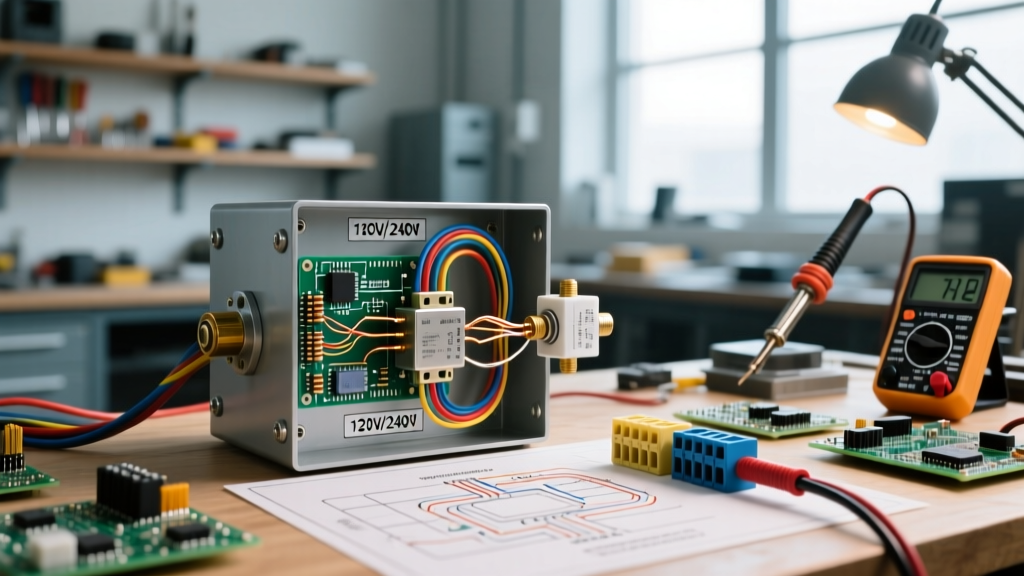

Mastering the Wiring Diagram for Pressure Switch on Air Compressor Installations
The pressure switch is the central nervous system of any pneumatic system. It dictates when the motor engages, when it cuts out, and crucially, how the system depressurizes for the next start cycle. Whether you are retrofitting an older 60-gallon shop compressor or commissioning a new 5-horsepower industrial unit, relying on a generic schematic is a recipe for welded contacts or motor burnout. This installation planning guide provides a comprehensive wiring diagram for pressure switch on air compressor setups, focusing on real-world single-phase and three-phase applications, precise terminal mappings, and critical unloader valve integration.
Critical Safety Directive: Before removing any terminal covers, execute a full Lockout/Tagout (LOTO) procedure. According to OSHA's Hazardous Energy Control standards, verifying the absence of voltage with a CAT III or CAT IV rated multimeter (such as the Fluke 117) is mandatory. Furthermore, air compressor motors utilize start and run capacitors that can retain lethal charges long after power is disconnected. Always discharge capacitors using a 20,000-ohm, 5-watt bleeder resistor before touching any internal wiring.
Phase 1: Pre-Installation Planning and Component Sizing
Before pulling wire, you must match the pressure switch to the motor's specific electrical profile. The most common mistake DIYers make is sizing the switch based on the motor's Full Load Amps (FLA). In reality, the switch contacts must be rated to handle the motor's Locked Rotor Amps (LRA)—the massive inrush current that occurs during startup, which can be 5 to 7 times higher than the FLA.
2026 Switch Selection Matrix
As of 2026, the market is dominated by a few heavy-duty NEMA-rated switches. Below is a planning matrix to help you select the correct unit for your specific compressor architecture:
| Manufacturer & Model | Voltage / Phase | Max HP Rating | Unloader Type | Approx. Cost (2026) |
|---|---|---|---|---|
| Square D 9013FHG12J59M1 | 240V / 1-Phase | 2 HP | Integral Mechanical (1/4" flare) | $38 - $45 |
| Furnas 69PJ14 | 240V / 1-Phase | 5 HP | Pilot Valve / Solenoid | $75 - $95 |
| Condor MDR 3/11 | 240V-575V / 3-Phase | 7.5 HP | Integrated 3-Phase | $120 - $150 |
| Square D 9013FSG2 | 120V-240V / 1-Phase | 2 HP (at 230V) | Standard Mechanical | $25 - $32 |
Phase 2: Decoding the Terminal Architecture
Understanding the terminal layout is the core of interpreting any wiring diagram for pressure switch on air compressor configurations. While designs vary slightly between Schneider Electric's Square D lineup and legacy Furnas models, the fundamental nomenclature remains standardized across the industry.
- Line Terminals (L1, L2, L3): These are the incoming power connections from your main disconnect or circuit breaker panel. L1 and L2 are used for single-phase 240V; L1, L2, and L3 are used for three-phase applications.
- Load Terminals (T1, T2, T3): These route power out to the motor contactor or directly to the motor windings.
- Grounding Lug (Green Screw): A dedicated, clearly marked terminal for the equipment grounding conductor (EGC). Never use a standard terminal screw for grounding.
- Auxiliary Contacts (NC / NO): Found on heavier-duty switches (like the Furnas 69PJ series), these Normally Closed or Normally Open contacts are used to trigger external electrical unloader solenoids or indicator lights.
Phase 3: Execution - Wiring a 240V Single-Phase System
The 240V single-phase setup is the standard for 60-gallon to 80-gallon stationary shop compressors (typically 3 HP to 5 HP). This configuration requires a dedicated double-pole breaker. For a 30-amp circuit, use 10 AWG THHN wire in conduit, or 10/2 SOOW flexible cord if the switch features an integrated strain relief fitting. As of 2026, 10 AWG copper THHN averages around $0.85 per foot, making proper conduit planning essential to minimize waste.
Step-by-Step 240V Wiring Sequence
- Prepare the Conductors: Strip exactly 5/8-inch of insulation from the 10 AWG wires. Do not nick the copper, as this creates a hot spot under load.
- Land the Line Side: Connect the two hot wires from the breaker panel to the L1 and L2 terminals. (In 240V single-phase, polarity between L1 and L2 does not matter).
- Land the Load Side: Connect the two hot wires leading to the motor to the T1 and T2 terminals.
- Secure the Ground: Route the bare copper or green insulated ground wire to the designated green grounding lug. If using a metal enclosure, ensure the switch chassis is bonded to the ground via the mounting screws or a dedicated bonding jumper.
- Apply Precise Torque: Using an inch-pound torque screwdriver, tighten all terminal screws to the manufacturer's specification—typically 14 to 18 in-lbs for standard 10 AWG terminals. Under-torquing causes arcing; over-torquing strips the brass threads.
Phase 4: Unloader Valve Circuit Integration
A wiring diagram for pressure switch on air compressor setups is incomplete without addressing the unloader valve. When the compressor reaches cut-out pressure, the switch opens the circuit to stop the motor. Simultaneously, it must vent the trapped air in the discharge line between the pump head and the tank check valve. If this air is not vented, the motor will attempt to restart against high head pressure, resulting in a locked rotor condition, tripped breakers, or burnt start windings.
Mechanical vs. Electrical Unloaders
For switches like the Square D 9013FHG series, the unloader is purely mechanical. A small brass pin inside the switch actuator physically pushes open a 1/4" flare pilot valve when the switch trips to the 'OFF' position. No electrical wiring is required for the unloader in this scenario; you simply connect the copper or nylon pilot tube from the check valve to the switch's unloader port.
For larger 5 HP+ systems utilizing a magnetic motor starter, the pressure switch acts only as a pilot signal device. In this wiring configuration:
- The pressure switch's Normally Closed (NC) auxiliary contacts are wired in series with the motor starter's coil circuit.
- When the switch opens at cut-out pressure, it de-energizes the starter coil.
- A secondary Normally Open (NO) contact block, mechanically linked to the switch, closes simultaneously to energize a 120V or 240V blow-down solenoid valve, venting the pilot line electrically.
Phase 5: Compliance and Environmental Considerations
Proper wire routing and enclosure selection are heavily scrutinized during electrical inspections. According to the National Electrical Code (NFPA 70), flexible cords (like SOOW) cannot be used as a substitute for fixed wiring where subject to physical damage. If your compressor is located in a high-traffic shop aisle, you must use rigid metal conduit (RMC) or intermediate metal conduit (IMC) with liquid-tight flexible metal connectors (LFMC) at the switch knockout to absorb motor vibration.
Furthermore, ensure your switch enclosure matches the environment. A standard NEMA 1 enclosure is sufficient for clean, dry indoor shops. However, if you are installing the compressor in an auto bay, agricultural setting, or wash-down area, you must specify a NEMA 4 or NEMA 4X pressure switch to prevent metallic dust or moisture from causing a short circuit across the L1 and T1 terminals.
Troubleshooting Common Installation Failures
Even with a perfect wiring diagram for pressure switch on air compressor execution, mechanical and electrical edge cases can arise during commissioning. Use this diagnostic framework to resolve them:
- Switch Chattering (Rapid Cycling): If the switch rapidly clicks on and off at the cut-out pressure, the differential spring (the smaller spring inside the switch) is set too tight, or there is a massive air leak in the pilot tube. Adjust the differential screw counter-clockwise to widen the gap between cut-in and cut-out pressures to at least 20 PSI.
- Motor Hums but Won't Start: This is almost always an unloader failure. The switch is sending power to the motor (T1/T2 are hot), but the mechanical unloader pin is bent or the solenoid coil is burnt out, leaving head pressure trapped. Disconnect the pilot tube at the check valve and manually cycle the switch to verify the pin travels fully outward.
- Burnt or Pitted Contacts: If you open a switch after a few months and find black, pitted copper on L1/T1, the switch is undersized for the motor's LRA, or the terminal screws were not torqued to spec, creating high resistance and localized heating. Always verify the switch's HP rating matches or exceeds the motor nameplate.
Final Commissioning Checklist
Before re-energizing the system, perform a final visual and mechanical audit. Verify that no stray copper strands are bridging the gap between the Line and Load terminals. Ensure the switch cover is securely fastened with all original screws to maintain the NEMA enclosure rating. Finally, stand clear of the pressure relief valve, engage the main disconnect, and monitor the first two start-stop cycles with a clamp meter to ensure the startup amperage drops smoothly back to the motor's rated FLA within three seconds.