
The True Cost of Downtime and the Role of Schematics
In heavy manufacturing and automated processing, unplanned downtime costs an average of $260,000 per hour. When a conveyor halts, a packaging machine faults, or a safety circuit trips, guessing is not an option. The first and most critical line of defense is the plc electrical wiring diagram. This document is not just a map for initial panel assembly; it is your primary diagnostic tool for isolating faults, verifying signal integrity, and restoring operations safely. In this guide, we will dissect how to leverage modern schematics to troubleshoot Programmable Logic Controller (PLC) systems, focusing on real-world failure modes, I/O tracing, and edge cases that routinely trap inexperienced technicians.
Anatomy of a Modern PLC Electrical Wiring Diagram
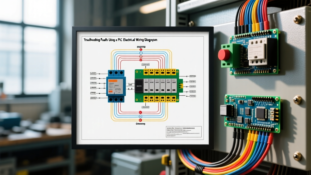
Before grabbing a multimeter, you must understand how modern schematics are structured. Adhering to standards like IEC 61082 or NFPA 79, a professional plc electrical wiring diagram is typically divided into distinct functional zones, often organized vertically or horizontally with cross-reference grids.
1. Power Distribution and Conditioning
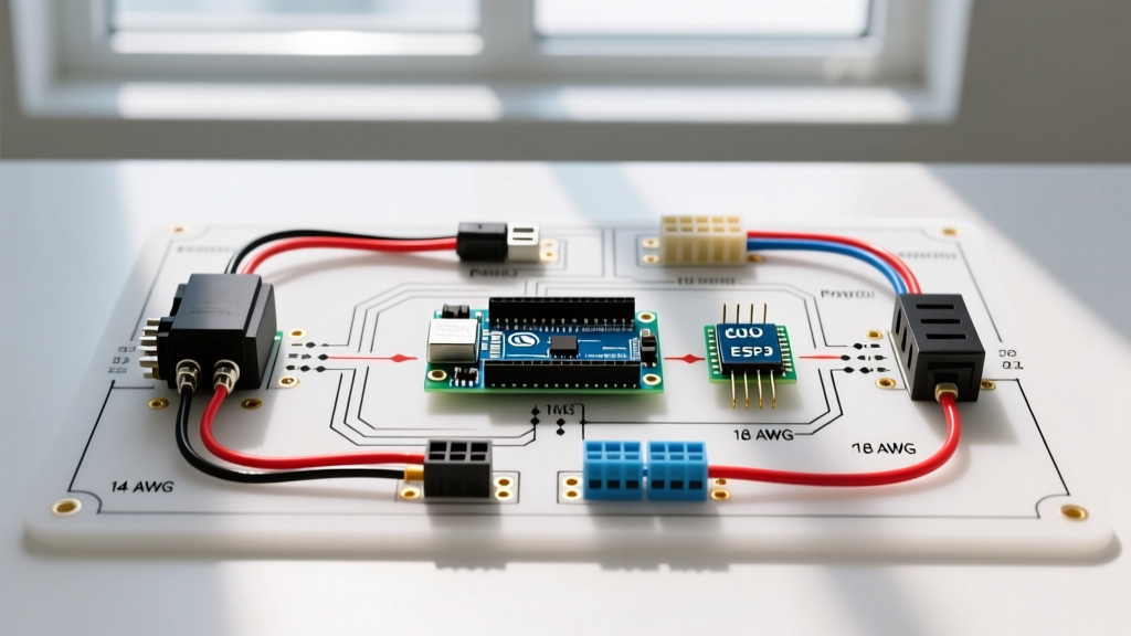
The first section details the main disconnect, branch circuit protection, and power supply units (PSUs). For a standard 24VDC control circuit, you will see the primary AC feed entering a DIN-rail mounted PSU (such as a Phoenix Contact QUINT4 or Siemens SITOP). The diagram will specify the exact wire gauge (typically 14 AWG for 10A+ feeds) and the ferrule crimp specifications. Troubleshooting starts here: if the PLC is completely dead, the diagram tells you exactly which circuit breaker (e.g., CB1) and which PSU terminals (L+/M) to test first.
2. Input and Output (I/O) Mapping
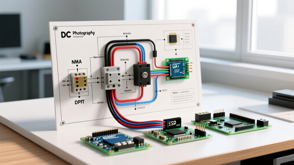
The core of the diagram maps field devices to specific PLC terminals. A high-quality schematic will include the PLC tag name (e.g., I:0/0 or %I0.0), the physical terminal number, the wire color code, and the destination device. When a proximity sensor fails to trigger, the diagram allows you to trace the signal from the sensor's M12 connector, through the intermediate junction box, to the exact pin on the PLC input card.
Sinking vs. Sourcing: The Most Common Wiring Trap
One of the most frequent errors encountered when troubleshooting or retrofitting panels is a mismatch between sensor output types and PLC input configurations. A plc electrical wiring diagram will explicitly state whether the input card is sinking (current flows into the card) or sourcing (current flows out of the card). Misinterpreting this leads to dead inputs or, worse, shorted internal opto-isolators.
| Sensor Type | Output Behavior | Required PLC Input Type | Common PLC Examples (24VDC) |
|---|---|---|---|
| PNP (Sourcing) | Switches +24VDC to the signal wire | Sinking (Current flows into PLC) | Siemens S7-1200 (6ES7214-1AG40-0XB0), AB 1769-IQ16 |
| NPN (Sinking) | Switches 0VDC (Common) to the signal wire | Sourcing (Current flows out of PLC) | Omron NX1P, older Allen-Bradley MicroLogix DC inputs |
Diagnostic Tip: If your plc electrical wiring diagram specifies a PNP sensor but the input LED on the PLC illuminates weakly or erratically, check for a floating common. Sinking inputs require a solid 0VDC reference at the PLC's COM/M terminal. Use your multimeter to measure between the sensor's 0V reference and the PLC's M terminal; it should read less than 0.2V. Anything higher indicates a high-resistance connection or a missing jumper.
Step-by-Step Troubleshooting Workflow
When a machine faults, follow this systematic approach using your schematic to isolate the issue efficiently.
- Verify the Power Supply Tolerance: Set your digital multimeter (DMM) to DC Voltage. Measure directly at the PLC's VDC and COM terminals, not at the power supply. A 24VDC system must operate within a tight tolerance (typically 20.4V to 28.8V). If you read 24.1V at the PSU but only 21.5V at the PLC, your diagram will help you identify the undersized wire run or loose terminal block causing the voltage drop.
- Trace the Input Signal: Identify the faulted input tag in the PLC software. Locate the corresponding physical terminal on the plc electrical wiring diagram. Force the field device (e.g., manually trigger the limit switch). Measure the voltage at the PLC terminal. If you have 24VDC (for a sinking input) but the PLC software shows a '0', the internal opto-isolator is likely blown. If you have 0V, the fault is upstream—use the diagram's wire numbers to check intermediate terminal blocks.
- Check Output Load Integrity: If the PLC software shows an output as '1' and the LED is illuminated, but the contactor doesn't pull in, measure the voltage at the output terminal. A reading of 0V under load indicates a blown internal fuse or a tripped thermal protector on the output card. A reading of 24V at the PLC but 0V at the coil means you have an open circuit in the field wiring.
- Verify Network Terminations: For communication faults (e.g., PROFINET or EtherNet/IP drops), the diagram will show the network topology. Check for missing termination resistors (typically 120-ohm for RS485/Modbus) or improper star-topology wiring on daisy-chained Ethernet segments.
Real-World Edge Cases and Failure Modes
Standard troubleshooting assumes clean power and perfect wiring. In reality, industrial environments are hostile. Here are two advanced edge cases where the plc electrical wiring diagram is essential for diagnosis.
Inductive Kickback on Solid-State Outputs
Solid-state PLC outputs (transistors) are highly susceptible to voltage spikes generated by inductive loads like solenoid valves and relay coils. When the output turns off, the collapsing magnetic field generates a reverse voltage spike that can easily exceed 100V, instantly destroying the output transistor. A properly engineered plc electrical wiring diagram will specify a flyback diode (e.g., 1N4007) wired in reverse bias across the coil. If a specific output channel keeps failing every few weeks, check the diagram and the physical panel to ensure the suppression diode hasn't failed open or was omitted during assembly.
Phantom Analog Readings from VFD Noise
Variable Frequency Drives (VFDs) generate massive electromagnetic interference (EMI). If your 4-20mA analog input (e.g., a pressure transmitter) is reading erratically, the issue is often a ground loop or unshielded wiring. The diagram should specify a shielded twisted-pair cable (like Belden 3106A).
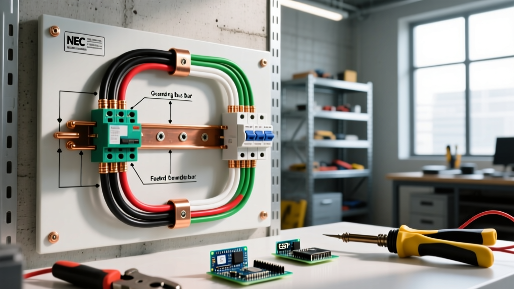
Expert Rule for Shield Grounding: The cable shield must be grounded at one end only—typically at the PLC cabinet's dedicated analog ground bar. If the plc electrical wiring diagram shows the shield grounded at both the sensor end and the PLC end, you have created a ground loop. Cut the shield connection at the field device end and terminate it with heat shrink tubing.
Essential Diagnostic Tools for 2026
To effectively execute the troubleshooting steps outlined above, you need reliable, industrial-grade test equipment. Relying on cheap, uncalibrated meters can lead to misdiagnosed PLC modules (which cost between $300 and $1,200 to replace).
- Fluke 87V Industrial Multimeter: The gold standard for measuring DC voltage drops and checking continuity. Its low-impedance (LoZ) mode is critical for identifying 'ghost voltages' on floating PLC inputs.
- Fluke 1587 Insulation Multimeter: Essential for testing motor and solenoid winding insulation. A shorted solenoid coil might draw enough current to trip the PLC output's internal protection without blowing the main branch fuse.
- Weidmüller PZ 4 Ferrule Crimper: While not a diagnostic tool, poor crimps cause 40% of intermittent panel faults. If your troubleshooting reveals a loose wire, re-crimping it with a proper quad-crimper ensures a gas-tight connection that won't vibrate loose.
Conclusion
A plc electrical wiring diagram is far more than a construction blueprint; it is the foundational logic map for all maintenance and troubleshooting activities. By understanding power distribution zones, mastering the nuances of sinking and sourcing I/O, and systematically tracing signals with a high-quality multimeter, you can reduce machine downtime from hours to minutes. Always cross-reference your physical findings with the schematic, adhere to NFPA 79 standards for industrial machinery, and consult manufacturer resources like the Siemens Industry Online Support portal for module-specific fault codes. For more advanced diagnostics, review the Fluke electrical troubleshooting guides to keep your testing methodologies sharp and accurate.