
The Critical Role of Precision Wiring in Access Control
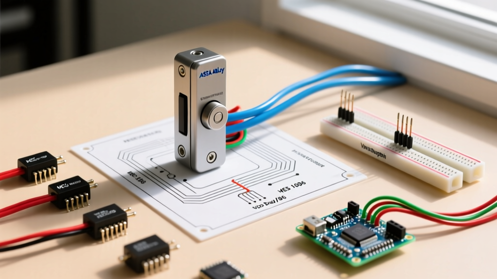
When deploying commercial access control systems, the physical layer is where most failures occur. An ASSA ABLOY electric strike wiring diagram is not just a schematic; it is a blueprint for life safety, security, and hardware longevity. Whether you are installing a heavy-duty HES 1006 for a high-traffic exterior door or a medium-duty Von Duprin 6300 for an interior office suite, improper wiring leads to voltage drop, fried access control board relays, and compromised egress paths.
In this 2026 comprehensive walkthrough, we will dissect the exact wiring topologies required for ASSA ABLOY group strikes, focusing on power supply sizing, back-EMF suppression, and fail-safe versus fail-secure configurations.
Understanding ASSA ABLOY Strike Architectures
Before pulling wire, you must define the operational mode of your strike. ASSA ABLOY manufactures strikes across multiple brands (HES, Von Duprin, Securitron), but the electrical principles remain consistent.
Fail-Secure vs. Fail-Safe (Life Safety Implications)
According to the NFPA 101 Life Safety Code, the choice between fail-secure and fail-safe is dictated by the door's role in the building's egress plan.
- Fail-Secure (Default Locked): When power is removed, the strike remains locked. Used on exterior perimeter doors or secure server rooms. Typically wired as 12VDC or 24VDC standard solenoids.
- Fail-Safe (Default Unlocked): When power is removed, the strike unlocks to allow free egress. Mandatory for stairwell doors and fire-rated egress paths. Often utilizes continuous duty coils or magnetic locks, though ASSA ABLOY offers specific fail-safe strike models (e.g., HES 1006FS).
Expert Note: Never wire a fail-secure strike on a door that serves as a primary fire exit unless it is integrated with a monitored fire alarm system that physically cuts power to the strike via a dedicated relay during an alarm event.
Pre-Installation: Wire Gauge and Power Sizing
The most common cause of electric strike failure is voltage drop over long wire runs. A HES 1006 requires a minimum of 12VDC at the coil to reliably overcome the 1,500 lbs of holding force and internal spring tension during the initial 'breakaway' moment. If your access control board outputs 12VDC but the wire run is 150 feet using 18 AWG wire, the voltage at the strike may drop below 9VDC, resulting in a 'clicking' sound without retraction.
Wire Gauge vs. Distance Matrix (12VDC Systems)
| Wire Gauge (AWG) | Max Distance (One Way) | Max Current Draw Supported | Recommended Use Case |
|---|---|---|---|
| 18 AWG | 50 feet | 0.4A | Standard interior doors, short runs to local power supply |
| 16 AWG | 100 feet | 0.6A | Extended office corridors, standard commercial runs |
| 14 AWG | 200 feet | 1.0A | Large campuses, remote parking structures, high-draw strikes |
| 12 AWG | 350+ feet | 1.5A+ | Extreme distances; consider 24VDC strikes to reduce gauge needs |
Step-by-Step Wiring Walkthrough: HES 1006 & Von Duprin 6300
The following steps assume you are using a standard access control panel (such as a HID VertX or Mercury LP4502) with a dedicated Form C relay, and a centralized linear power supply like an Altronix SMP3 or Securitron BPS-12-5.
Step 1: Power Supply to Access Control Board
- Run 16 AWG or 14 AWG wire from your centralized power supply's 12VDC (or 24VDC) output to the access control panel's main power input terminals.
- Connect the power supply ground to the panel's common ground bus. Do not skip the ground bonding; floating grounds cause data communication errors on RS-485 lines.
- Verify voltage at the panel's auxiliary power output terminals with a multimeter. It should read between 12.2V and 12.8V under no load.
Step 2: Panel Relay to Electric Strike
Most commercial strikes are wired through the panel's Form C relay to allow the software to control the power state.
- Connect a jumper wire from the Panel's AUX Power (+) terminal to the Common (C) terminal of the strike's assigned relay.
- Connect a wire from the relay's Normally Open (NO) terminal to the Positive (+) wire of the ASSA ABLOY electric strike.
- Connect the strike's Negative (-) wire directly back to the Panel's AUX Ground (-) terminal.
When the access control software grants access, the relay energizes, closing the circuit between C and NO, sending 12VDC to the strike coil.
Step 3: Back-EMF Suppression (The #1 Cause of Board Failure)
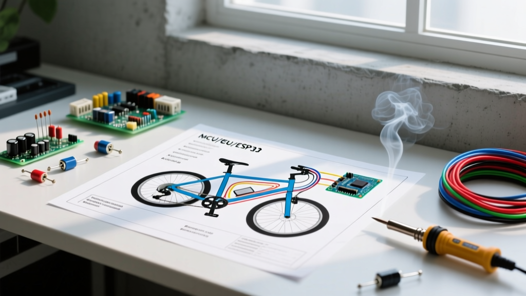
When the relay opens and power is cut to the strike's solenoid, the collapsing magnetic field generates a massive reverse voltage spike (Back-Electromotive Force or Back-EMF). This spike can exceed 100V for a fraction of a millisecond, instantly frying the access control board's relay contacts or microprocessor.
- The Fix: Install a flyback diode (e.g., 1N4004 or 1N4007) directly across the strike's two wires.
- Orientation is Critical: The diode must be wired in reverse bias. The silver band (cathode) of the diode must point toward the Positive (+) wire, and the black end (anode) must point toward the Negative (-) wire.
- If wired backward, the diode will create a dead short across the power supply the moment the relay closes, blowing the power supply fuse or destroying the board trace.
For installations following strict Security Industry Association (SIA) integration standards, using a Metal Oxide Varistor (MOV) alongside the diode is recommended for heavy-duty strikes like the HES 1006 to clamp transient spikes even faster.
Step 4: Integrating DPS and REX Sensors
Modern ASSA ABLOY strikes often include integrated Door Position Switches (DPS). The DPS is a separate, dry-contact reed switch that tells the panel if the door is physically closed.
- Locate the two DPS wires (usually white and green, distinct from the red/black solenoid wires).
- Wire these to a dedicated supervised input zone on your access control panel.
- Configure the panel software to trigger a 'Door Forced Open' alarm if the DPS opens without a preceding REX (Request to Exit) or card read event.
Real-World Troubleshooting & Failure Modes
Even with a perfect ASSA ABLOY electric strike wiring diagram on paper, field conditions introduce variables. Here is how to diagnose the most common 2026 field issues:
The Strike 'Clicks' but the Keeper Won't Retract
Root Cause: Voltage drop or mechanical binding. The solenoid has enough power to move the internal plunger slightly (the click), but not enough amperage to overcome the mechanical friction of the keeper.
Solution: Measure voltage at the strike coil while the relay is energized. If it drops below 11VDC, upgrade your wire gauge. Additionally, check the door alignment; if the latch is binding against the strike lip, the internal friction will exceed the solenoid's pull force.
Loud AC Buzzing from a DC Strike
Root Cause: You are feeding Alternating Current (AC) into a Direct Current (DC) solenoid. This happens when installers mistakenly tap into a 12VAC transformer meant for an analog camera or older HVAC thermostat.
Solution: Verify the power source with a multimeter set to AC and DC. A DC strike on an AC source will rapidly overheat, melt the internal coil insulation, and fail permanently. Replace the strike and correct the power supply.
Access Control Board Relay Keeps Frying
Root Cause: Missing or incorrectly oriented flyback diode, or the strike is drawing more inrush current than the board's relay rating (typically 2A max for standard panels).
Solution: Verify the 1N4007 diode orientation. If the strike is a high-inrush 24VDC model, bypass the board's internal relay entirely and use the board's low-current trigger output to switch an external heavy-duty relay (like an Altronix R104) located near the power supply.
2026 Component Pricing & Procurement Guide
Budgeting for commercial access control requires accurate hardware estimates. Below is the current 2026 market pricing for standard ASSA ABLOY group components and necessary wiring accessories.
| Component | Model / Spec | Avg. 2026 Price (USD) |
|---|---|---|
| Heavy Duty Electric Strike | HES 1006 (12/24VDC) | $295.00 - $340.00 |
| Medium Duty Electric Strike | Von Duprin 6300 | $230.00 - $265.00 |
| Linear Power Supply (4 Door) | Altronix SMP3 | $145.00 - $160.00 |
| Flyback Diode Pack | 1N4007 (10-pack) | $4.50 - $6.00 |
| Plenum Rated Wire (1000ft) | 16 AWG 2-Conductor Shielded | $180.00 - $210.00 |
Final Inspection and Compliance
Before closing the door frame and finalizing the ASSA ABLOY installation, always perform a mechanical and electrical stress test. Cycle the door 50 times using the access control software to ensure the power supply does not thermally shut down under repeated inrush loads. Verify that the door closes securely from a 10-degree open position without latching failure.
For comprehensive guidelines on how electric strikes integrate with fire-rated assemblies, always consult the latest ASSA ABLOY Security Doors documentation and ensure your local Authority Having Jurisdiction (AHJ) approves the specific fail-safe/fail-secure configuration for your building's life safety plan. Proper wiring is not just about making the door open; it is about ensuring the system performs flawlessly when lives and assets are on the line.