
Understanding the 24-Volt Series Architecture
Planning a 24-volt trolling motor installation requires more than just connecting batteries; it demands precise attention to voltage drop, marine-grade corrosion resistance, and strict adherence to safety standards. Whether you are rigging a Minn Kota Ultrex 80, a Garmin Force, or a Lowrance Ghost, this installation planning guide provides the exact wiring diagram for 12 24 volt trolling motor configurations. By wiring two 12V marine batteries in series, you double the system voltage to 24V while maintaining the original amp-hour (Ah) capacity of a single battery. This architecture is essential for delivering the high thrust required for heavy bass boats, pontoons, and offshore saltwater skiffs without overloading standard 12V marine electrical systems.
Why Series Instead of Parallel?
In a parallel configuration, voltage remains at 12V while capacity (Ah) doubles. However, a 24V trolling motor requires 24 volts to operate its internal brushed or brushless DC motor efficiently. If you wire in parallel, the motor will not engage, and you risk damaging the control board. A series circuit connects the positive terminal of the first battery to the motor, and the negative terminal of the second battery to the motor, bridging the remaining two terminals together. According to the American Boat & Yacht Council (ABYC), series wiring for marine propulsion must utilize identical battery chemistries, capacities, and ages to prevent reverse-charging and thermal runaway.
Component Sizing and Selection Matrix
Undersized wiring is the leading cause of trolling motor failure, resulting in severe voltage drop, melted insulation, and tripped breakers. The Minn Kota Rigging Manuals and ABYC E-11 standards dictate that wire gauge must be selected based on the total one-way distance from the battery bank to the motor receptacle, factoring in a 3% maximum voltage drop. Below is the definitive sizing matrix for 24V systems drawing up to 56 amps continuously.
| Total Wire Run (One-Way) | Recommended Wire Gauge | Max Continuous Amps | Required Circuit Breaker |
|---|---|---|---|
| Under 15 feet | 6 AWG Marine Tinned | 60A | 60-Amp Inline Reset |
| 15 to 20 feet | 4 AWG Marine Tinned | 70A | 60-Amp Inline Reset |
| 20 to 25 feet | 2 AWG Marine Tinned | 95A | 60-Amp or 70-Amp Reset |
| Over 25 feet | 1/0 AWG Marine Tinned | 120A | 70-Amp or 80-Amp Reset |
Expert Note: Never use standard automotive copper wire for marine applications. You must use marine-grade tinned copper wire (such as Ancor or Genuinedealz). The tin coating prevents galvanic corrosion and black wire syndrome, which increases resistance and causes voltage drop over time.
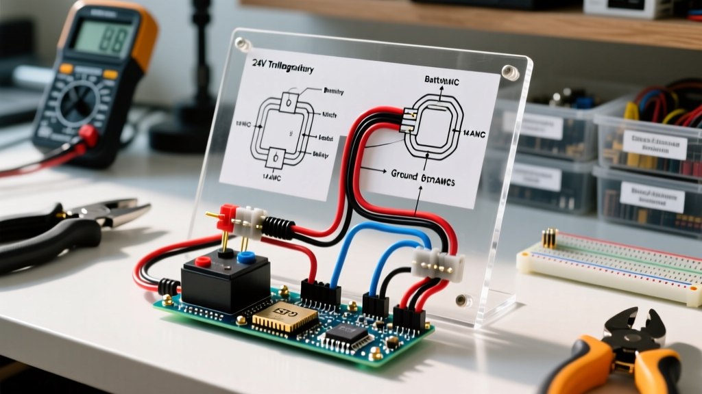
Step-by-Step Wiring Diagram for 12 24 Volt Trolling Motor
Follow this precise sequence to ensure a safe, ABYC-compliant 24V installation. Before beginning, disconnect all shore power and ensure the boat's main battery switch is in the OFF position.
Step 1: Battery Placement and Preparation
Place your two 12V batteries (e.g., Group 31 AGM or 12V Lithium Iron Phosphate) in a dedicated, ventilated battery box or compartment. Ensure they are secured with marine-grade tie-down straps to prevent shifting in rough chop. Clean the battery terminals with a stainless steel wire brush and apply a thin layer of dielectric grease or NO-OX-ID A-Special to prevent oxidation. Torque all terminal nuts to the manufacturer's specification—typically 120 in-lbs for 5/16-inch studs.
Step 2: The Series Jumper Connection
This is the most critical step in the wiring diagram for 12 24 volt trolling motor setups. Cut a short length of your selected gauge marine wire (e.g., 2 AWG) to bridge the two batteries. Crimp a 5/16-inch ring terminal on both ends using a heavy-duty hexagonal crimping tool like the Knipex 97 51 10 or IWISS IWS-16. Connect this jumper from the Negative (-) terminal of Battery 1 to the Positive (+) terminal of Battery 2. Seal the crimps with 3M Marine Adhesive Sealant 5200 or dual-wall heat shrink tubing to block moisture ingress.
Step 3: Routing and Sizing the Marine Wire
Measure the exact distance from the Positive (+) terminal of Battery 1 to the trolling motor plug receptacle at the bow. Add 10% to this measurement to account for bends and drip loops. Cut your positive and negative main run wires. Route the wires through the boat's rigging tubes, using split loom tubing and cable ties every 18 inches to prevent chafing against fiberglass or aluminum hulls.
Step 4: Installing the Inline Circuit Breaker
ABYC standards require a circuit breaker within 7 inches of the positive battery terminal. Mount a Blue Sea Systems 60A Surface Mount Circuit Breaker (Model 7182) on a non-conductive backing plate near Battery 1. Connect the positive wire from Battery 1 to the breaker's input stud, and run the output side of the breaker all the way to the positive pin on your bow receptacle. This protects the entire positive run from short circuits.
Step 5: Completing the Circuit and Receptacle Wiring
Connect the negative wire from the Negative (-) terminal of Battery 2 directly to the negative pin on the bow receptacle. If you are using an Anderson Powerpole connector or a Minn Kota MKR-19 quick-disconnect plug, ensure the pins are oriented correctly to prevent reverse polarity. Reverse polarity will instantly destroy the trolling motor's logic board. Use a digital multimeter to verify the voltage at the bow receptacle before plugging in the motor; it should read between 25.2V and 26.8V for fully charged AGM/Lithium batteries.
Calculating Voltage Drop for Edge Cases
For custom boat builds or exceptionally long wire runs, rely on the standard voltage drop formula to verify your wire gauge selection. The formula is: VD = (2 x L x I x R) / 1000, where L is the one-way length in feet, I is the maximum current draw (e.g., 56A for an 80lb thrust motor), and R is the resistance per 1000 feet of the chosen wire gauge (found in NEC Chapter 9, Table 8). If your calculated voltage drop exceeds 3% of 24V (which is 0.72V), you must step up to the next thickest wire gauge.
Critical Failure Modes to Avoid in 2026
- Soldering Marine Connections: Never solder high-vibration, high-amperage marine battery connections. Solder creates a rigid joint that work-hardens and fractures under the constant pounding of a boat hull. Always use mechanical hex-crimps with adhesive-lined heat shrink.
- Using 12V Automotive Breakers: Standard automotive breakers are not ignition-protected. In a marine environment, a spark from a tripping automotive breaker can ignite trapped bilge gases. Always use USCG Type Accepted and SAE J1171 ignition-protected marine breakers.
- Mixing Battery Chemistries: Do not wire a 12V Lead-Acid battery in series with a 12V Lithium battery. Their differing charge/discharge curves and internal BMS (Battery Management System) cutoffs will cause severe voltage imbalances, potentially triggering the lithium BMS to shut down mid-tournament.
Real-World 2026 Cost Breakdown
Budgeting for a premium, tournament-ready 24V trolling motor installation requires factoring in marine-grade components. Below is a realistic cost estimate for a 20-foot bass boat rigging setup.
| Component | Specification | Estimated Cost (USD) |
|---|---|---|
| Marine Wire | Ancor 2 AWG Tinned Copper (30 ft) | $115.00 |
| Circuit Breaker | Blue Sea Systems 60A (Ignition Protected) | $38.50 |
| Terminals & Heat Shrink | 3/8' & 5/16' Adhesive-Lined Ring Terminals | $24.00 |
| Quick Disconnect Plug | Minn Kota MKR-19 or Anderson 175A SB50 | $45.00 |
| Onboard Charger | Minn Kota MK 220E (2-Bank, 10A per bank) | $189.99 |
| Total Rigging Hardware | Excludes Batteries and Motor | $412.49 |
Expert FAQ
Can I use a standard 12V battery charger on my 24V series setup?
No. You must use a 2-bank onboard marine charger (like the Minn Kota MK 220E or NOCO GENPRO2 20A). A 2-bank charger independently monitors and charges each 12V battery in the series circuit, ensuring both batteries reach full capacity without overcharging one and undercharging the other.
Do I need to wire the trolling motor to the boat's main ground bus?
The trolling motor circuit should remain isolated from the boat's 12V accessory ground bus to prevent ground loops and electrical noise that can interfere with sensitive sonar transducers and GPS units. The 24V circuit must be a closed loop returning directly to Battery 2.
What happens if my series jumper wire is thinner than the main run wires?
The series jumper carries the exact same amperage as the main positive and negative run wires. Therefore, the jumper must be the exact same gauge (e.g., 2 AWG) as the main wires. Using a thinner jumper creates a bottleneck, generating excessive heat and risking a fire hazard.