
The Critical Role of Interconnected Hardwired Alarms
When a fire breaks out, you have less than three minutes to escape. According to the National Fire Protection Association (NFPA), interconnected smoke alarms reduce the risk of dying in a reported home fire by 50%. Unlike standalone battery units, a hardwired system ensures that when one detector senses smoke, every unit in the dwelling sounds simultaneously. Understanding the correct wiring diagram for smoke alarms is not just a best practice; it is a strict requirement under NFPA 72 and modern building codes.
This appliance wiring tutorial provides a comprehensive, electrician-grade breakdown of how to rough-in, wire, and terminate a 120V interconnected smoke alarm circuit. We will cover specific wire gauges, modern dual-sensor unit compatibility, and the edge cases that cause nuisance tripping on Arc-Fault Circuit Interrupter (AFCI) breakers.
Materials and Component Specifications
Before pulling any wire, you must gather the correct materials. Using undersized wire or mismatched interconnect brands is a leading cause of system failure and code violations.
Wire and Electrical Components
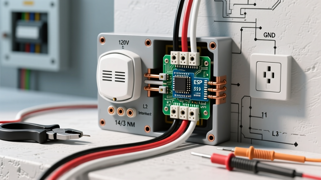
- Cable: 14/3 NM-B (Non-Metallic Sheathed) cable with a ground. The black wire is the 120V hot, the white is the neutral, and the red is the interconnect signal wire. Current 2026 pricing for Southwire 14/3 NM-B averages $0.65 to $0.85 per linear foot.
- Breaker: 15-Amp single-pole AFCI breaker. As of recent NEC updates, smoke alarms installed in bedrooms or branching from bedroom circuits must be AFCI protected.
- Boxes: 4-inch octagonal or round ceiling boxes, minimum 12.5 cubic inches to accommodate the wire nuts and alarm pigtails.
- Connectors: Yellow wire nuts (ideal for joining three 14 AWG wires) or push-in WAGO 221 series connectors for faster, vibration-resistant terminations.
Recommended 120V Smoke Alarm Models
You cannot mix different manufacturers on a hardwired interconnect line due to proprietary signaling voltages. Stick to a single brand for the entire circuit.
- Kidde PI2010: A hardwired 120V dual-sensor (photoelectric and ionization) alarm with a battery backup. Retails for $28–$35 per unit. Excellent for minimizing kitchen nuisance alarms.
- First Alert SA9120B: A reliable 120V ionization alarm with a 9V battery backup. Highly cost-effective at $15–$20 per unit, best suited for bedrooms and hallways.
Decoding the 120V Wiring Diagram for Smoke Alarms
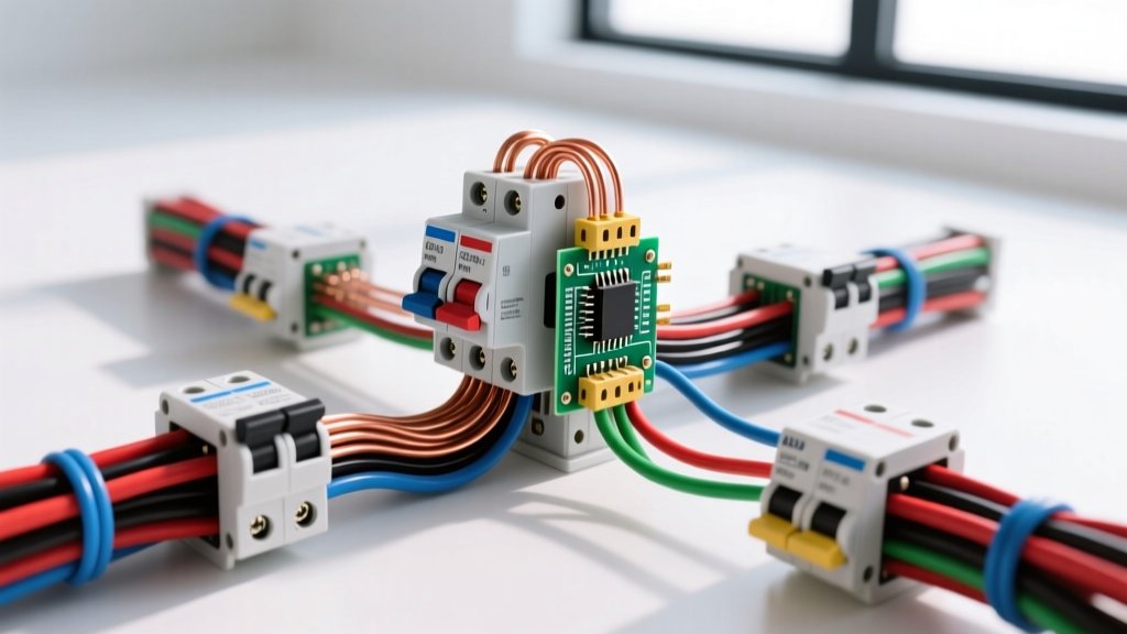
The standard wiring diagram for hardwired smoke alarms relies on a daisy-chain topology. Power originates at the electrical panel, travels to the first smoke alarm, and then continues to subsequent alarms via the 14/3 cable.
⚠️ CRITICAL SAFETY WARNING: Always turn off the main breaker and verify the circuit is dead using a non-contact voltage tester (like the Klein Tools NCVT-2) before opening any junction box. Never assume a wire is safe based solely on wall switch positions.
The Three-Wire Logic
| Wire Color | Function | Connection Point | Voltage / Signal |
|---|---|---|---|
| Black | Line / Hot | Connects to the Black pigtail wire on the alarm harness. | 120V AC continuous |
| White | Neutral | Connects to the White pigtail wire on the alarm harness. | 0V (Return path) |
| Red | Interconnect | Connects to the Red pigtail wire. Carries the 9V DC trigger signal to downstream units. | 9V DC signal when tripped |
Step-by-Step Rough-In and Termination Guide
Follow this precise sequence to ensure a clean installation that passes municipal electrical inspections.
- Run the 14/3 NM-B Cable: Start at the panel and run the cable to the first ceiling box. From the first box, run another length of 14/3 to the second box, and so on. Leave at least 8 inches of slack protruding from each ceiling box.
- Strip the Sheathing: Use a Romex ripper to remove the outer PVC jacket, exposing exactly 1/2 inch of insulation on the individual black, white, and red conductors. Do not nick the copper.
- Terminate the Neutrals (White): At the first box, connect the incoming white wire, the outgoing white wire (to the next alarm), and the white pigtail from the smoke alarm harness using a yellow wire nut. Twist clockwise until tight.
- Terminate the Hots (Black): Connect the incoming black, outgoing black, and the alarm's black pigtail. Note: If the circuit continues to a standard light fixture after the last alarm, the black wire continues, but the red interconnect wire stops at the final alarm.
- Terminate the Interconnect (Red): Connect the incoming red, outgoing red, and the alarm's red pigtail. Cap the red wire with a wire nut at the very last alarm on the circuit, as it has nowhere else to send the signal.
- Grounding: Connect the bare copper ground wires together and to the metal ceiling box (if applicable). Most modern plastic smoke alarm pigtails do not require a ground connection, but the circuit ground must remain continuous.
- Mount and Test: Plug the harness into the alarm, twist the unit onto the mounting bracket, and restore power. Press the 'Test' button on the first unit; all interconnected units must sound within 2 seconds.
Hardwired vs. Wireless Interconnect: A 2026 Comparison Matrix
While hardwiring is the gold standard for new construction, retrofitting older homes can be cost-prohibitive. Here is how modern hardwired setups compare to wireless mesh networks in 2026.
| Feature | Hardwired 120V Interconnect | Wireless Mesh Interconnect (e.g., Kidde Wireless) |
|---|---|---|
| Installation Cost | High ($300-$600+ for professional retrofit) | Low ($50-$80 per battery-operated unit) |
| Reliability | Exceptional (Physical copper connection) | High (RF mesh, but susceptible to thick masonry/lathe) |
| Code Compliance (New Build) | Mandatory under IRC / NFPA 72 | Generally not accepted for new construction |
| Maintenance | Replace 9V backup battery annually | Replace primary AA/Lithium batteries every 1-2 years |
Advanced Troubleshooting and Edge Cases
Even with a perfect wiring diagram for smoke alarms, field conditions can introduce complex issues. Here is how to diagnose the most common edge cases.
1. Nuisance Tripping on AFCI Breakers
If your smoke alarm circuit is protected by an AFCI breaker and trips randomly, the issue is often not the alarm itself. Older smoke alarms with cheap switching power supplies can introduce harmonic noise back onto the line, which the AFCI interprets as an arc fault. Solution: Upgrade to modern units (like the Kidde PI2010) with filtered power supplies, or move the smoke alarms to a dedicated, non-AFCI protected circuit if local code permits (e.g., placing them on a hallway lighting circuit that is exempt from AFCI requirements in your specific municipality).
2. The 'Ghost' Chirp (Intermittent Beeping)
A single chirp every 40 seconds usually indicates a low backup battery. However, if you have replaced the battery and the chirping persists across multiple units, you likely have a voltage drop on the interconnect line. This happens if you exceed the maximum number of devices. NFPA 72 limits interconnected smoke alarms to 18 devices on a single circuit (with no more than 12 being smoke detectors; the rest can be CO or heat detectors). Exceeding this causes the 9V DC signal to degrade, causing downstream units to fault.
3. Mixed Manufacturer Incompatibility
If you wire a First Alert unit into a daisy-chain of Kidde units, the interconnect will fail. First Alert and Kidde use different DC signaling protocols on the red wire. The First Alert unit will sound when it detects smoke, but it will not send the correct voltage trigger to the Kidde units. Always audit the entire circuit and standardize on one manufacturer.
Code Compliance and Authoritative References
Proper installation goes beyond following a diagram; it requires adherence to national and local safety codes. For the most accurate and up-to-date placement rules (such as the requirement to install alarms inside every sleeping room, outside each separate sleeping area, and on every level of the home), consult the following authoritative resources:
- National Fire Protection Association (NFPA): The NFPA provides exhaustive guidelines on smoke alarm placement, interconnectivity requirements, and maintenance schedules. Review their official safety tip sheets at the NFPA Smoke Alarms Public Education Portal.
- U.S. Fire Administration (USFA): For statistical data on fire prevention and federal recommendations on residential alarm topologies, refer to the USFA Smoke Alarm Outreach Guidelines.
- Consumer Product Safety Commission (CPSC): The CPSC tracks product recalls and safety hazards related to specific alarm models and battery failures. Check their Smoke Alarm Safety Guides before purchasing bulk units for large residential projects.
By strictly following this 120V wiring diagram for smoke alarms, utilizing 14/3 NM-B cable, and respecting manufacturer interconnect limits, you will build a life-safety system that is robust, code-compliant, and capable of protecting occupants when seconds truly matter.