
Mastering the Washing Machine Schematic: A Troubleshooting Blueprint
When a modern washing machine fails mid-cycle, guessing which component failed is a costly and frustrating endeavor. Whether you are servicing a traditional top-load agitator model like the Whirlpool WTW5000DW or a sophisticated direct-drive front-loader like the LG WM3700HWA, the manufacturer's schematic is your most powerful diagnostic tool. Learning how to properly interpret a wiring diagram for washing machine repairs transforms a chaotic teardown into a logical, step-by-step electrical trace.
As of 2026, the appliance repair industry has shifted heavily toward Brushless DC (BLDC) motors and IoT-enabled Electronic Control Boards (ECBs). This means physical component swapping is no longer effective without verifying DC logic signals and sensor feedback loops. This guide will teach you how to read the schematic, trace voltage paths, and isolate faults using a digital multimeter (DMM) with absolute precision.
Anatomy of the Schematic: Decoding the Legend
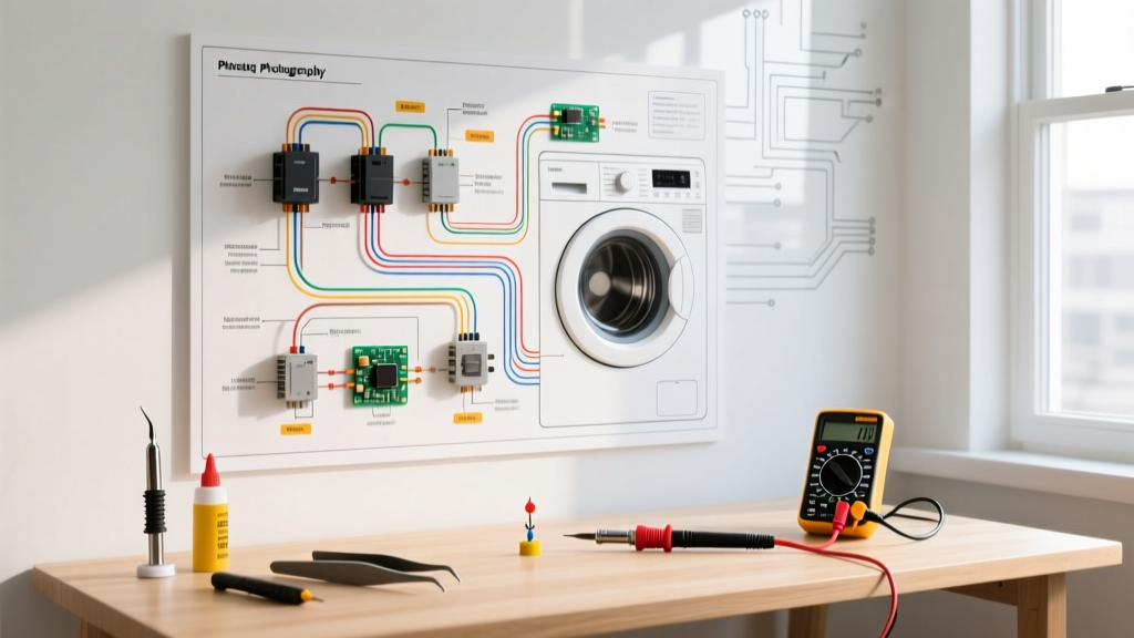
Before touching a screwdriver, you must understand the visual language of the schematic. Most North American washing machines operate on a 120VAC, 60Hz single-phase supply, though some high-capacity models and dryers require 240VAC. The diagram will universally feature the following elements:
- Line Voltage (L1 and Neutral): L1 (typically a black wire) carries the 120VAC hot leg. Neutral (typically a white wire) completes the circuit. In schematics, L1 is usually drawn on the left or top, and Neutral on the right or bottom.
- Switches and Contacts: Represented by parallel lines. A normally open (NO) switch is drawn with a gap; a normally closed (NC) switch is drawn with the contacts overlapping.
- Loads (Motors, Valves, Heaters): Represented by circles with specific letter designations (e.g., 'M' for Motor, 'V' for Valve, 'H' for Heater).
- Wire Color Codes: The schematic legend maps wire colors to specific harness pins. For example, a wire labeled 'BU' is Blue, 'RD' is Red, and 'GN/YL' is Green with a Yellow stripe.
The Tech Sheet Hunt: Where to Find the Diagram
Manufacturers do not include full schematics in the user manual. Instead, they provide a 'Tech Sheet' hidden inside the appliance. Here is where to find them on major 2026 models:
- Whirlpool / Maytag (Top Load): Usually folded inside a plastic sleeve taped to the back of the front console panel, or tucked into a slot on the inner tub wall.
- LG (Front Load): Typically located inside the lower front access panel, taped to the floor pan, or behind the main control panel.
- Samsung: Often found inside the top panel, taped to the underside of the metal chassis near the EMI filter.
Step-by-Step Troubleshooting with the Diagram
Let us apply the schematic to three of the most common washing machine failures. For these tests, you will need a reliable True-RMS multimeter, such as the Fluke 117, set to the appropriate Ohms (Ω) or AC/DC Voltage settings.
Fault 1: Washer Will Not Agitate or Spin (Motor Circuit)
The Symptom: The tub fills with water, but the motor remains dead silent. No humming, no clicking.
The Schematic Trace:
- Locate the motor circuit on the diagram. Trace the L1 line from the power cord to the lid switch (or door lock assembly).
- Test the Lid Switch: Unplug the machine. Set your DMM to Ohms. Probe the lid switch terminals. With the lid closed, the meter should read 0.00Ω (continuity). If it reads 'OL' (Open Line), the switch is dead. Replace it.
- Trace to the Timer/ECB: If the lid switch is good, trace the line to the control board output relay. Plug the machine back in, set the DMM to AC Volts, and carefully probe the board's motor output terminals during the spin cycle. You should read 120VAC.
- Test the Motor Windings: If the board outputs 120VAC but the motor does not run, unplug the machine and test the motor. Disconnect the harness. Probe the start and run windings. A healthy run winding typically reads 1.0Ω to 3.0Ω, while the start winding reads 3.0Ω to 10.0Ω. An 'OL' reading indicates a burnt internal winding.
Fault 2: No Cold Water Fill (Water Inlet Valve)
The Symptom: The machine turns on, the timer advances, but no water enters the tub on a cold wash setting.
The Schematic Trace:
- Find the Water Inlet Valve (WIV) section on the diagram. Identify the solenoid coil labeled for the 'Cold' valve.
- Test the Solenoid Coil: Unplug the washer. Disconnect the wire harness from the cold water solenoid. Place your DMM probes on the two spade terminals of the valve. A healthy solenoid coil should read between 500Ω and 1,500Ω. If it reads 'OL', the internal copper winding is broken. If it reads near 0Ω, it is shorted.
- Verify ECB Voltage: If the coil is good, the issue is upstream. Reconnect the harness, plug in the machine, and probe the harness connector pins for 120VAC when the machine calls for water. No voltage means a failed ECB relay or a faulty water level pressure switch preventing the fill signal.
Fault 3: Washer Won't Drain (Pump Motor Circuit)
The Symptom: The wash cycle completes, but the tub remains full of water. The cycle halts with a drain error code (e.g., 'OE' on LG, 'F9 E1' on Whirlpool).
The Schematic Trace:
- Locate the drain pump motor on the schematic. Note that many modern drain pumps are synchronous AC motors, while some high-end 2026 models use DC brushless pumps.
- Test the Pump Windings: Unplug the unit. Access the pump (usually via the lower front panel). Disconnect the wires and measure resistance. A standard AC drain pump should read between 10Ω and 20Ω. A reading of 'OL' means the pump is dead.
- Check for Physical Obstructions: Before replacing the pump, manually spin the impeller. If it is seized by a stray coin or bra wire, the motor will overheat and trip its internal thermal fuse, which will also show as 'OL' on your multimeter.
Component Resistance Reference Matrix
Keep this matrix handy when tracing faults. These values represent standard North American 120VAC washing machine components. Always refer to your specific model's tech sheet, as variations exist.
| Component | Expected Resistance (Ohms) | Common Failure Mode |
|---|---|---|
| Water Inlet Valve Solenoid | 500Ω - 1,500Ω | Coil burns out (reads OL) or shorts (reads <50Ω) |
| Drain Pump Motor (AC) | 10Ω - 20Ω | Impeller seizes, thermal fuse blows (reads OL) |
| Lid Switch / Door Lock | 0Ω (Closed) / OL (Open) | Internal contacts carbonize, preventing continuity |
| Motor Start Winding | 3.0Ω - 10.0Ω | Overheating melts insulation, causing short to ground |
| Motor Run Winding | 1.0Ω - 3.0Ω | Centrifugal switch fails to engage start winding |
| NTC Thermistor (Water Temp) | ~10,000Ω (at 77°F / 25°C) | Moisture ingress causes erratic resistance drops |
Decoding Modern Electronic Control Board (ECB) Schematics
If you are working on a 2026 direct-drive model, the schematic will look vastly different from legacy diagrams. Instead of simple 120VAC lines routing through mechanical timers, you will see complex DC logic circuits.
Modern ECBs use a Hall Effect Sensor to track the rotor position of the BLDC motor. The schematic will show three low-voltage DC lines (typically 5V, Ground, and Signal) running from the stator harness to the main board. If the washer spins erratically or stops mid-cycle, use your DMM's DC Voltage setting to check for a steady 5VDC reference signal at the board harness. If the 5V reference is missing, the ECB's internal voltage regulator has failed, requiring a full board replacement (typically costing between $180 and $320 depending on the brand).
Additionally, modern machines rely heavily on NTC thermistors for water temperature control. Unlike mechanical thermostats that simply open and close, thermistors change resistance inversely with temperature. The schematic will provide a temperature-to-resistance chart. If the washer refuses to heat the water, test the thermistor. If it reads 10kΩ at room temperature but fails to drop to roughly 2kΩ when placed in 140°F water, the sensor is defective.
Critical Safety Protocols: Lockout and Capacitor Discharge
Troubleshooting live circuits carries inherent risks. According to OSHA's Control of Hazardous Energy guidelines, proper lockout/tagout (LOTO) procedures must be followed before removing any physical panels or touching bare wire terminals. Always disconnect the appliance from the wall receptacle or trip the dedicated circuit breaker at the main panel before performing resistance (Ohms) tests.
Furthermore, adherence to the NFPA 70 National Electrical Code dictates that all major appliances must have a dedicated equipment grounding conductor. Never bypass the ground pin on a washing machine plug to fit an older two-prong outlet; this creates a severe shock hazard in a wet environment.
Expert Warning: The EMI Filter Capacitor Hazard
Even when unplugged, the Electromagnetic Interference (EMI) filter board located where the power cord enters the machine can store a lethal charge of 120VAC or more in its capacitors. Before touching any internal wiring, discharge the EMI filter by bridging the Line and Neutral terminals on the board's input side using a 20,000-ohm, 5-watt power resistor. Never use a standard screwdriver to short the terminals, as this can weld the screwdriver to the contacts and destroy the board's trace paths.
Final Thoughts on Diagram-Driven Diagnostics
Relying on a wiring diagram for washing machine troubleshooting is the hallmark of a professional technician. By systematically tracing voltage paths, verifying component resistance against known matrices, and understanding the transition from AC line voltage to DC logic signals, you eliminate guesswork. As appliance efficiency standards continue to tighten—as outlined in ENERGY STAR appliance specifications—the complexity of these schematics will only increase. Mastering the schematic today ensures you can confidently diagnose the smart, sensor-driven washers of tomorrow.