
The Hidden Cost of Ignoring Wire Gauge in Microcontrollers
When transitioning an Arduino project from a solderless breadboard to a permanent perfboard or custom PCB enclosure, most makers fall into a dangerous trap: they use the exact same 28 AWG (American Wire Gauge) jumper wires for every single connection. While 28 AWG is perfectly adequate for low-current I2C or SPI data lines, using it for power rails, motor drivers, or high-draw LED arrays is a recipe for catastrophic voltage drops and logic errors.
According to standard copper resistivity tables, 28 AWG wire has a resistance of approximately 64.9 milliohms per foot. If you run a 3-foot round-trip from your Arduino's 5V rail to a NEMA 17 stepper motor driver drawing 1.5A, you will lose nearly 0.3V across the wire. This sag can drop your logic high voltage below the threshold required by the ATmega328P microcontroller, triggering random brownouts and ghost resets.
This is exactly why utilizing professional arduino wiring diagram software is critical. By digitally mapping your wire gauges and standardizing your color codes before you ever pick up a wire stripper, you eliminate physical guesswork, ensure NEC-aligned safety margins, and create documentation that allows you to troubleshoot the system months later.
Top Arduino Wiring Diagram Software for Gauge and Color Mapping
Not all schematic capture tools handle physical wire properties equally. When your primary goal is documenting physical point-to-point wiring (rather than just etching a PCB), you need software that allows custom visual and metadata assignments for individual wires. Here is how the top three platforms compare in 2026 for this specific use case.
| Software | Pricing (2026) | Wire Gauge Mapping | Color Code Customization | Best For |
|---|---|---|---|---|
| Fritzing | $8.00 (One-time) | Visual thickness only (requires text annotation) | Excellent (Full RGB/Hex picker) | Breadboard-to-Perfboard visual documentation |
| KiCad (v8/v9) | Free / Open Source | Advanced (Net Classes define exact mm/AWG widths) | Moderate (Limited to default schematic palette) | Professional PCB design & complex harness mapping |
| QElectroTech | Free / Open Source | Excellent (Native industrial cable/gauge tagging) | Good (Customizable element properties) | Industrial control panels & heavy relay wiring |
Why Dedicated Arduino Wiring Diagram Software Matters for AWG
While drawing tools like Adobe Illustrator or Visio allow you to draw lines, they lack the underlying electrical metadata. Dedicated arduino wiring diagram software like Fritzing or KiCad understands the electrical context. In KiCad, for example, you can assign a 'Net Class' to your 5V and GND nets, forcing the schematic and PCB layout to visually and mathematically enforce a minimum track width equivalent to 20 AWG, preventing you from accidentally routing a high-current path through a 0.2mm trace.
Standardizing DC Color Codes: Beyond Random Jumper Wires
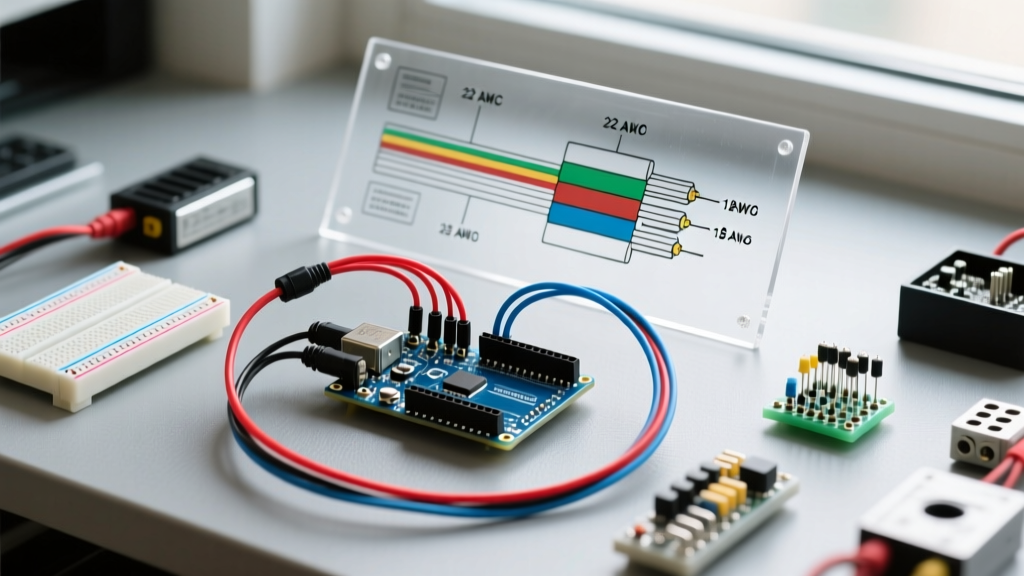
In the maker community, wire color is often an afterthought. However, adopting a strict color code standard—adapted from the DIN 47100 standard for multi-core cables and standard DC automotive practices—drastically reduces debugging time. When you configure your wiring diagram software, assign these specific Hex color codes to your virtual wires to match the physical silicone or PVC wire you will purchase.
| Function / Net | Standard Color | Hex Code for Software | Recommended AWG | Stranding Type |
|---|---|---|---|---|
| Main Power (+12V / +24V) | Yellow | #FFD700 | 18 AWG - 16 AWG | Stranded (Flex) |
| Logic Power (+5V) | Red | #FF0000 | 22 AWG | Stranded |
| Logic Power (+3.3V) | Orange | #FFA500 | 24 AWG | Stranded |
| Ground (GND) | Black | #000000 | 20 AWG (Oversized) | Stranded |
| I2C SDA / SPI MISO | Blue | #0000FF | 26 AWG - 28 AWG | Solid or Stranded |
| I2C SCL / SPI SCK | Green | #008000 | 26 AWG - 28 AWG | Solid or Stranded |
| Analog Signals | White | #FFFFFF | 28 AWG (Shielded) | Shielded Twisted Pair |
Expert Note: Always oversize your Ground (GND) wires by at least 2 AWG compared to your positive voltage rails. Ground return paths carry the cumulative return current of all parallel circuits; a thin GND wire will cause 'ground bounce,' introducing noise into your Arduino's analog-to-digital converter (ADC) readings.
Step-by-Step: Configuring Fritzing for AWG and Color Documentation
Fritzing remains the most accessible arduino wiring diagram software for physical breadboard and point-to-point wiring visualization. However, it does not natively map visual wire thickness to exact AWG numbers. Here is the professional workflow to enforce gauge documentation:
- Set the Visual Baseline: Click on your wire. In the Inspector panel, adjust the 'Thickness' slider. Use 0.5mm for 28 AWG data lines, 1.0mm for 22 AWG logic power, and 2.0mm for 16 AWG motor power.
- Apply the Hex Color: In the same Inspector panel, click the color swatch and input the exact Hex codes from the table above. This ensures your digital diagram perfectly matches your physical wire spools.
- Add AWG Text Annotations: Because Fritzing lacks an automated AWG tag generator, use the Text tool (T) to place a small, 8pt label next to every major power harness. Format it as:
[RED] 22 AWG - 5V Rail. - Export the BOM: When generating your Bill of Materials, Fritzing will list 'Wire' as a generic component. You must manually edit the exported CSV to reflect the specific gauge and color purchased (e.g., '22 AWG Silicone Wire - Red - 5 meters').
Defining Net Classes in KiCad for Harness Mapping
If your Arduino project involves a custom shield or a complex wire harness connecting multiple boards, KiCad is the superior choice. By utilizing Net Classes, you can enforce wire gauge rules at the schematic level.
- Open the Schematic Editor and navigate to File > Board Setup > Net Classes.
- Create a new class named
POWER_12V. Set the clearance and track width to reflect a 16 AWG equivalent (approx 1.29mm diameter, so use a 1.5mm track width for safety margins). - Create a second class named
SIGNAL_I2C. Set the track width to 0.25mm (approx 28 AWG). - Assign your +12V and GND nets to the
POWER_12Vclass, and your SDA/SCL nets to theSIGNAL_I2Cclass. - When you generate your schematic PDF, KiCad will visually differentiate the line weights, providing an instant visual cue to the assembler regarding which physical wire gauge to pull from the spool.
Troubleshooting Common Wiring Failures via Diagram Audits
Even with the best arduino wiring diagram software, physical execution can introduce errors. Here are three common failure modes related to gauge and color mismanagement, and how to spot them in your diagrams:
- The I2C Capacitance Trap: If your diagram shows 28 AWG wires for an I2C bus, but the physical routing exceeds 1 meter, the parasitic capacitance of the thin, closely-spaced wires will degrade the signal edges. Fix: Update the diagram to specify 24 AWG twisted pair with a 4.7kΩ pull-up resistor network.
- Servo Brownouts: A diagram showing 4 micro-servos powered directly from the Arduino's 5V pin using 24 AWG wire. Micro-servos can draw 800mA each during stall. The Arduino's onboard linear regulator will overheat and shut down. Fix: Redraw the diagram to route servo power directly from a dedicated 5V BEC (Battery Eliminator Circuit) using 18 AWG wire, sharing only the GND and PWM signal lines with the Arduino.
- Thermal Melting at Crimps: Using 16 AWG wire for a high-current heater, but terminating it with standard Dupont connectors rated for 3A. The wire is fine, but the connector will melt. Fix: Annotate the diagram to specify JST-XH or Molex Micro-Fit 3.0 connectors for high-current nodes.
Pro-Tip for 2026 Enclosure Builds: When documenting point-to-point wiring in an enclosure, always specify the use of ferrules on the ends of stranded wire before they enter screw terminals. Stranded 20 AWG wire splayed out in a terminal block creates a high-resistance point that can arc and cause a fire. Your wiring diagram should include a note: 'All stranded terminations require crimped ferrules.'
By treating your arduino wiring diagram software not just as a drawing tool, but as a strict engineering ledger for wire gauge and color codes, you bridge the gap between hobbyist tinkering and professional electromechanical assembly. The result is a system that is safer, easier to debug, and built to survive long-term deployment.