
Why SPAL Fans Demand Dedicated Breaker Panel Integration
Upgrading to a high-performance cooling system is one of the most effective modifications for high-horsepower builds, tight engine bays, and low-speed off-road crawling. However, simply bolting on a premium fan is only half the battle. As vehicle electrical architectures evolve in 2026, managing high-amperage DC loads requires meticulous attention to power distribution. A standard spal electric fan wiring diagram provides the logical flow of the circuit, but it is the physical integration with your vehicle's auxiliary breaker panel that dictates long-term reliability and fire safety.
SPAL Automotive fans are notorious for their massive air displacement, which inherently requires high-torque, high-draw electric motors. For example, the popular SPAL 30102113 (16-inch, 2025 CFM) pulls a continuous 18.5 amps, but its inrush current upon startup can spike to 45 amps for several hundred milliseconds. If your breaker panel and wire gauge are not spec'd to handle this transient spike, you will experience nuisance tripping, melted relay contacts, or catastrophic voltage drop that starves your ECU of stable voltage.
The Anatomy of a High-Amp SPAL Electric Fan Wiring Diagram
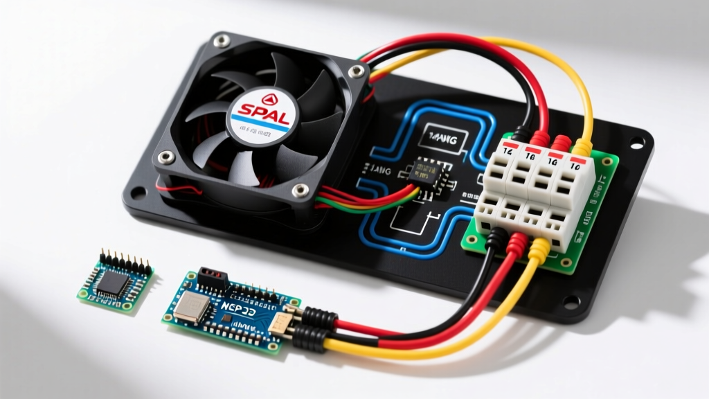
Before routing wires to your fuse block, you must understand the core logic of the circuit. A robust SPAL setup never routes main power through the thermostat switch or the cabin toggle. Instead, it utilizes a heavy-duty, 4-post Bosch-style relay to isolate the high-current motor feed from the low-current trigger signal.
- Pin 30 (Power In): Fed directly from the auxiliary breaker panel or main battery bus bar via heavy-gauge TXL wire.
- Pin 87 (Power Out): Delivers the protected high-current feed directly to the SPAL fan's positive terminal.
- Pin 86 (Ground): Secured to a clean, bare-metal chassis ground or routed back to the battery negative terminal.
- Pin 85 (Trigger In): Receives a 12V+ signal from your thermostat probe, trinary AC switch, or manual dashboard toggle.
By using this topology, the thermostat switch only carries a fraction of an amp, drastically extending the life of your switches and preventing dashboard wiring harness fires.
Breaker and Wire Sizing Matrix for Popular SPAL Models
Selecting the correct circuit breaker and wire gauge is a function of both the continuous amperage draw and the physical length of the wire run. The table below provides exact specifications for the most common SPAL puller fans. Note that wire gauges are calculated based on a standard 10-foot one-way run from the breaker panel to the relay and fan.
| SPAL Model Number | Fan Size & CFM | Continuous Draw | Inrush Spike | Recommended Breaker | Wire Gauge (AWG) | Relay Rating |
|---|---|---|---|---|---|---|
| 30100325 | 11' Puller (1300 CFM) | 14.5A | ~35A | 20A Slow-Blow | 12 AWG TXL | 40A Standard |
| 30102044 | 14' Puller (1860 CFM) | 16.5A | ~40A | 25A Slow-Blow | 10 AWG TXL | 40A Standard |
| 30102113 | 16' Puller (2025 CFM) | 18.5A | ~45A | 30A PTC / Slow-Blow | 10 AWG TXL | 50A Heavy Duty |
| 30103010 | Dual 11' (2720 CFM) | 28.0A | ~65A | 40A PTC / ANL Fuse | 8 AWG TXL | 70A Dual-Relay |
Auxiliary Panel Integration: Breakers vs. Fuses
When integrating a SPAL fan into your vehicle's electrical system, tapping into the factory ignition fuse block is a critical error. Factory panels are designed for low-draw OEM accessories, not 20-amp continuous motor loads. You must install a dedicated auxiliary breaker panel, such as the Blue Sea Systems ST Blade Secondary Fuse Block, wired directly to the alternator output stud or main battery terminal.
Managing Inrush Current with PTC Breakers
DC electric motors draw two to three times their rated continuous current to overcome initial rotor inertia. If you use a fast-acting standard automotive blade fuse, the inrush spike of a SPAL 16-inch fan will blow the fuse before the motor even reaches operating speed. To solve this, panel integrators must use PTC (Positive Temperature Coefficient) resettable circuit breakers or Time-Delay (Slow-Blow) fuses. According to Littelfuse DC circuit protection guidelines, time-delay fuses feature an internal thermal mass that absorbs the brief inrush spike without severing the circuit element, ensuring the fan starts reliably every time.
Step-by-Step Panel-to-Fan Wiring Procedure
Follow these exact steps to execute a professional-grade installation that meets SAE and IPC automotive wiring standards.
- Mount the Auxiliary Panel: Secure your secondary breaker panel within 18 inches of the battery or alternator output. Use 4 AWG battery cable to feed the panel's main bus bar, protected by a master 100A ANL fuse.
- Prepare the Main Feed: Cut a length of 10 AWG TXL (Cross-linked Polyethylene) wire. TXL is mandatory for engine bays due to its 125°C temperature rating and thin insulation profile. Strip the ends using a precision wire stripper to avoid nicking the copper strands.
- Terminate with Hex Crimps: Attach sealed ring terminals using a ratcheting hex crimp tool (such as the Knipex 97 50 61). Never use pliers. Apply dual-wall, adhesive-lined heat shrink over the crimp barrel to prevent moisture ingress and corrosion.
- Connect to the Breaker: Route the 10 AWG wire from the relay Pin 30 to the load side of your 30A PTC breaker on the auxiliary panel.
- Isolate the Trigger Circuit: If you are triggering the relay via the vehicle's A/C compressor clutch wire, solder a 1N4007 diode in-line on the trigger wire. This prevents voltage backfeed from the SPAL relay coil from damaging the ECU's A/C driver transistor.
Expert Warning: Never route a SPAL fan trigger signal directly from an ECU injector or ignition coil negative terminal without an opto-isolator or secondary relay. The inductive kickback from the fan relay coil can destroy sensitive ECU driver circuits instantly.
Advanced Integration: PWM Fan Controllers
For modern EFI builds where precise temperature management is critical, standard on/off relays cause massive temperature swings and repeated inrush current spikes. Upgrading to a PWM (Pulse Width Modulation) controller, like the SPAL PWM-V3, allows the fan to run at 40% speed during cruising and ramp to 100% only under heavy load. When wiring a PWM controller into your breaker panel, the main power feed must be sized for the absolute maximum continuous draw of the fan, and the breaker should be rated 15% higher than the max continuous draw to account for the high-frequency switching harmonics generated by the PWM unit.
Troubleshooting Voltage Drop and Nuisance Tripping
Even with a perfect spal electric fan wiring diagram, physical installation flaws can cause severe operational issues. If your fan operates sluggishly or your breaker trips randomly, perform a voltage drop test using a digital multimeter.
- Test the Breaker: Place your multimeter probes on either side of the circuit breaker while the fan is running. A reading above 0.15V indicates internal corrosion or an undersized breaker. Replace the breaker immediately.
- Test the Relay Contacts: Measure across Pin 30 and Pin 87. If you read more than 0.2V, the internal relay contacts are pitted from arcing. High-amperage SPAL fans will destroy cheap, overseas-manufactured relays in a matter of weeks. Always source relays from reputable manufacturers like Tyco or Bosch.
- Test the Ground Path: Measure between the fan's metal casing and the battery negative terminal. Any reading above 0.1V means your chassis ground is inadequate. Run a dedicated 10 AWG ground wire directly from the fan motor casing back to the engine block or battery negative.
Proper execution of your breaker panel integration ensures that your SPAL cooling system operates silently and reliably, keeping your engine temperatures stable whether you are idling in 100-degree traffic or pulling high-RPM passes on the track. For further reference on marine and automotive DC panel standards, consult the Blue Sea Systems circuit protection archives and the official SPAL USA technical documentation.