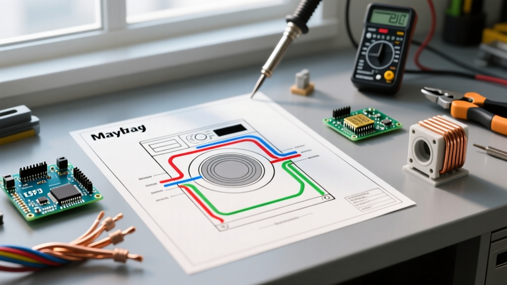

Mastering the Maytag Dryer Schematic: A Technician's Approach
When a Maytag dryer fails to heat, won't tumble, or throws an obscure F-code on the LED display, guessing which part to replace is a fast way to waste money. Modern Maytag dryers—manufactured by Whirlpool—rely on complex ladder-logic schematics rather than simple pictorial diagrams. Whether you are working on a popular electric model like the MED5030MW0 or a gas variant like the MGD6630HW0, understanding how to read the wiring diagram for Maytag dryer circuits is the single most valuable skill for DIY appliance repair.
Before touching a single wire, always perform a hard lockout. Unplug the dryer or flip the dedicated 240V double-pole breaker in your main panel. A standard digital multimeter (DMM), such as the Klein Tools MM400 (typically retailing around $45 in 2026), is all you need to trace voltage drops and test continuity against the manufacturer's schematic.
Safety Warning: Never bypass a thermal fuse or high-limit thermostat to 'test' if the dryer will run. Bypassing these safety devices removes the only barrier between a clogged vent and a structural house fire.
Decoding the Whirlpool/Maytag Wire Color Legend
The most common point of failure for DIYers reading a Maytag schematic is misinterpreting the wire color abbreviations. The wiring diagram uses a standardized two-letter code to denote the insulation color of the wire. When tracing a circuit from the terminal block to the control board, you must match these physical colors to the diagram.
- BK: Black (Usually L1, 120V or 240V hot)
- RD: Red (Usually L2, 240V hot for heating circuits)
- WT: White (Neutral, 120V return, or 240V center-tap)
- BU: Blue (Often used for motor start switches or control signals)
- GY: Gray (Common in sensor return lines)
- OR: Orange (Frequently used for the heating element relay or gas valve)
- VT: Violet (Timer or electronic control board logic)
- GN/YL: Green with Yellow stripe (Earth Ground)
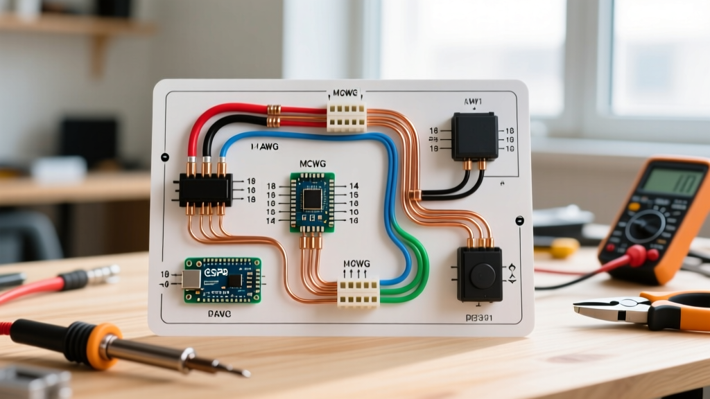
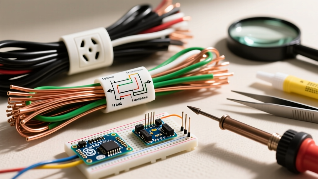
Furthermore, Maytag schematics denote wire gauge and temperature rating in small text next to the wire line (e.g., 14 AWG 105°C). If you ever need to splice or replace a burnt wire harness, you must match both the gauge and the high-temperature rating to prevent insulation meltdown inside the cabinet.
Tracing the 240V Electric Heating Circuit (MED Models)
The 'No Heat' complaint accounts for over 60% of electric dryer service calls. On an electric Maytag dryer, the heating element requires 240V to operate. This means it needs both L1 (Black) and L2 (Red) to complete the circuit. The wiring diagram maps this path through a series of safety thermostats and the motor's centrifugal switch.
Step-by-Step Circuit Tracing
- Locate L2 Input: Start at the terminal block where the Red (RD) wire enters the cabinet. Follow the RD wire on the diagram to the High-Limit Thermostat.
- Test the High-Limit: With the power off, disconnect the wires and test for continuity. It should read 0 ohms (closed). If it reads OL (open), the thermostat has tripped or failed.
- Trace to the Heating Element: The diagram shows the RD wire routing from the high-limit to one terminal of the heating element. The heating element itself should read between 10 and 50 ohms. (A common replacement part, WP8544771, costs about $35).
- The Centrifugal Switch Path: The other side of the heating element connects via a Black (BK) or Orange (OR) wire to the drive motor's centrifugal switch. This switch only closes when the motor reaches operational RPM. If the motor runs but the element gets no power, the centrifugal switch contacts are likely pitted or burnt.
- The Thermal Fuse and Cycling Thermostat: The circuit finally routes through the cycling thermostat and the thermal fuse (part WP3392519, roughly $12) before returning to the timer or electronic control board to complete the L1 path.
Component Testing Matrix: Expected Values
Use this reference table when probing components with your multimeter set to the Ohms (Ω) setting. Always isolate the component by removing at least one wire before testing to avoid reading parallel circuit resistance.
| Component | Expected Resistance | Common Failure Mode |
|---|---|---|
| Heating Element (Electric) | 10 Ω - 50 Ω | Coil breaks (OL) or shorts to chassis (0 Ω to ground) |
| Thermal Fuse | 0 Ω (Closed) | Blows due to restricted exhaust venting (OL) |
| High-Limit Thermostat | 0 Ω (Closed) | Trips from overheating, fails to reset (OL) |
| Cycling Thermostat | 0 Ω (Closed at room temp) | Internal bimetallic strip fatigues, causing under-heating |
| Thermistor (WP8577274) | ~10,000 Ω (at 70°F) | Resistance drifts, causing premature cycle termination |
| Drive Motor (Start Winding) | 2 Ω - 6 Ω | Winding shorts or centrifugal switch fails to engage |
Gas Dryer Specifics: Igniter and Valve Coils (MGD Models)
If you are troubleshooting a gas Maytag dryer, the wiring diagram shifts focus from a high-wattage heating element to a 120V igniter and a dual-coil gas valve assembly. The sequence of operation is strictly monitored by the flame sensor.
When the control board calls for heat, it sends 120V to the igniter. You should see the igniter glow brightly. According to the schematic, the igniter is wired in series with the flame sensor and the secondary gas valve coil. Once the igniter draws enough current (proving it is hot enough to ignite the gas), the flame sensor allows voltage to pass to the gas valve coils. The primary and secondary coils (often sold as kit 279834) open the gas gates. If the igniter glows but you hear no 'click' and smell no gas, use your multimeter to test the coils. The secondary coil should read roughly 1,000 to 2,000 ohms, while the primary coil usually reads between 300 and 500 ohms. If either reads OL, the coil is burnt out and must be replaced.
Electronic Control Board (CCU) Pinout Diagnostics
Modern Maytag dryers utilize a Central Control Unit (CCU) instead of mechanical timers. The wiring diagram for these models features a detailed pinout matrix for the CCU connectors (usually labeled P1, P2, P3, etc.).
When a dryer throws an 'F' code (like F-01 for primary control failure or F-22 for exhaust thermistor open), do not immediately replace the $180 control board. Use the schematic's pinout chart to test the wiring harness. For example, if the diagram shows the exhaust thermistor connects to Pin 3 (Red wire) and Pin 4 (Black wire) on the P2 connector, unplug the harness at the CCU and measure the resistance directly at those pins. If the reading is correct (approx 10k ohms at room temperature) but the board still throws the code, the board's internal analog-to-digital converter has failed. If the reading is OL at the board but correct at the sensor itself, you have a broken wire inside the harness—a much cheaper fix.
The 3-Prong to 4-Prong Grounding Strap Pitfall
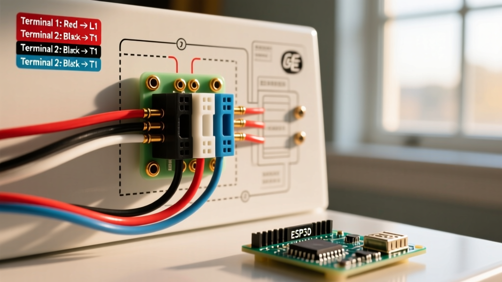
One of the most dangerous wiring errors occurs when homeowners install a used Maytag dryer and fail to configure the terminal block grounding strap correctly. Older homes may still have 3-prong 240V outlets, while modern codes require 4-prong outlets with a dedicated ground.
According to the National Fire Protection Association (NFPA) and NEC Article 250.140, the frame of the dryer must be grounded. On a 3-prong cord, the neutral (White) and the chassis ground are bonded together at the terminal block via a metal strap or a green ground wire. When converting to a 4-prong cord, you must remove this bonding strap and connect the separate Green ground wire to the chassis. Failing to remove the strap on a 4-prong setup causes return neutral current to flow through the dryer's metal chassis and your home's grounding system, creating a severe shock hazard and potential for electromagnetic interference with the CCU.
For further diagnostic assistance and to verify specific part numbers for your exact serial number, always cross-reference your findings with Maytag Official Support or consult community-driven repair databases like Appliance411 for legacy schematic archives.
Final Thoughts on Schematic Literacy
Reading a wiring diagram for a Maytag dryer is not about memorizing every wire; it is about understanding the logical flow of voltage and safety interlocks. By systematically tracing L1 and L2, verifying the state of the safety thermostats, and utilizing a reliable multimeter, you can accurately diagnose 95% of all dryer failures without resorting to the 'shotgun method' of parts replacement. Keep the schematic taped to the inside of the dryer's rear access panel—it is the ultimate roadmap for appliance longevity.