
Pole Barn Electrical Wiring Diagram: The Ultimate Installation Planning Guide
Wiring a post-frame building—commonly known as a pole barn—presents a unique set of electrical engineering challenges. Unlike a standard residential garage attached to a home, a detached pole barn requires its own dedicated feeder circuit, a properly sized subpanel, and a strict adherence to the National Electrical Code (NEC) regarding detached structure grounding. Whether you are building a workspace for a 240V MIG welder, an agricultural storage facility, or a hobbyist workshop, a well-planned pole barn electrical wiring diagram is the blueprint for a safe, code-compliant, and future-proof installation.
In this 2026 installation planning guide, we break down the exact load calculations, feeder cable selections, NEC grounding requirements, and branch circuit layouts you need to execute a flawless pole barn electrical rough-in.
Phase 1: Load Calculation and Subpanel Sizing
Before drawing a single line on your wiring diagram, you must calculate the anticipated electrical load. Undersizing your subpanel is the most common failure mode in DIY pole barn builds, leading to tripped main breakers and severe voltage drop when heavy machinery kicks on.
For a standard 30x40 foot workshop, a 100-amp subpanel is the minimum recommended starting point. However, if you plan to run a 5HP air compressor, an electric infrared heater, and a welder simultaneously, you should upgrade to a 125-amp or 150-amp subpanel.
Common Pole Barn Load Matrix
| Equipment / Appliance | Typical Amperage | Voltage | Recommended Circuit | Breaker Type |
|---|---|---|---|---|
| MIG Welder (140A-180A) | 30A - 40A | 240V | 8 AWG THHN / 10 AWG UF-B | 40A Double-Pole |
| 5HP Air Compressor | 28A - 32A | 240V | 8 AWG THHN | 40A Double-Pole |
| Infrared Tube Heater | 15A - 20A | 240V | 12 AWG THHN | 20A Double-Pole |
| LED High Bay Lighting (x6) | 4A - 6A (Total) | 120V | 14 AWG or 12 AWG | 15A or 20A Single-Pole |
| General Purpose Receptacles | 20A per circuit | 120V | 12 AWG THHN | 20A Single-Pole GFCI/AFCI |
Phase 2: Feeder Cable Selection and Trenching Specifications
The feeder cable connects your main service panel to the pole barn subpanel. Your wiring diagram must specify the exact cable type, gauge, and burial depth. As of 2026, copper prices remain volatile, making aluminum feeder cable the industry standard for detached outbuildings due to its cost-effectiveness and excellent conductivity when sized correctly.
Direct Burial (UF-B) vs. Conduit (THWN-2)
- Direct Burial (UF-B or URD): If you are using Underground Feeder cable (like 2-2-2-4 Aluminum URD), NEC Article 339 dictates a minimum burial depth of 24 inches. This method requires no conduit but offers less physical protection against future digging.
- PVC Conduit with THWN-2: Running individual THWN-2 conductors inside 1.5-inch or 2-inch Schedule 80 PVC conduit is the professional standard. NEC Table 300.5 requires a minimum burial depth of 18 inches for rigid nonmetallic conduit. This allows for future wire pulling if you ever need to upgrade the amperage.
Expert Tip on Voltage Drop: The NEC recommends a maximum 3% voltage drop on feeders. If your pole barn is more than 120 feet from the main panel, a standard #2 AWG aluminum feeder will suffer from excessive voltage drop, causing your welder to stutter and motors to overheat. Use the Southwire Voltage Drop Calculator to verify your run. For a 150-foot 100A run, upsize your aluminum feeder to 1/0 AWG (1-1-1-3) to maintain optimal voltage delivery.
Phase 3: Decoding the Core Wiring Diagram
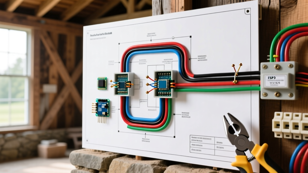
A proper pole barn electrical wiring diagram maps the flow of current from the main breaker to the subpanel's bus bars, emphasizing the critical separation of neutrals and grounds. Below is the logical flow of the schematic you must follow during installation.
- Main Panel Disconnect: A 100A double-pole breaker (e.g., Square D QO2100CP) is installed in the main service panel. The two hot legs (Phase A and Phase B) connect to the breaker, the neutral connects to the main neutral bus, and the ground connects to the main ground bus.
- The Feeder Run: Four conductors travel through the trench: two Hots (Black/Red), one Neutral (White), and one Equipment Grounding Conductor (Green or Bare).
- Subpanel Main Lugs: The two hot feeder wires terminate on the main lugs of the subpanel (e.g., Square D QO240L210PGC). The white neutral terminates on the isolated neutral bus bar.
- Ground Bus Termination: The bare/green equipment grounding conductor terminates on the separate ground bus bar.
The NEC 250.32 Grounding Rule for Detached Structures
The most heavily scrutinized aspect of any outbuilding wiring diagram by local inspectors is the grounding system. According to NFPA NEC 70 (Article 250.32), a detached building supplied by more than one branch circuit must have its own Grounding Electrode System.
- Isolate the Neutral: You must remove the green bonding screw or jumper strap in the subpanel. The neutral and ground bars must remain completely isolated in a detached subpanel to prevent objectionable neutral current from traveling back through the grounding path.
- Install Ground Rods: Drive two 8-foot, 5/8-inch copper-bonded ground rods into the earth outside the pole barn. They must be spaced at least 6 feet apart (NEC 250.53(A)(3)).
- Bond the Ground Bus: Connect a continuous 6 AWG bare copper wire from the ground rods to the subpanel's ground bus bar using an acorn ground clamp.
Phase 4: Branch Circuit Layout and Receptacle Planning
Once the subpanel is energized, your wiring diagram must detail the branch circuits. Pole barns are classified as damp or wet locations depending on their enclosure level, which heavily influences receptacle selection.
GFCI and AFCI Requirements
Under current NEC guidelines, all 125V, 15A, and 20A receptacles in a pole barn must be GFCI protected. Furthermore, if the pole barn is used as a workshop, AFCI (Arc-Fault Circuit Interrupter) protection is often required for lighting and receptacle circuits.
- Best Practice: Use GFCI/AFCI dual-function breakers at the subpanel rather than GFCI receptacles on the wall. This prevents nuisance tripping from dust and humidity inside the receptacle boxes and makes resetting easier.
- Weatherproof Covers: Any receptacle mounted on an exterior post or near an open bay door must feature an extra-duty, in-use weatherproof bubble cover (NEMA 3R rated). Refer to NEMA enclosure standards for proper housing classifications.
Lighting Circuit Design
Do not mix your lighting circuits with your heavy equipment circuits. If your air compressor kicks on and trips a breaker, you do not want to be left in the dark. Run a dedicated 120V, 20A lighting circuit using 12 AWG THHN wire in EMT conduit along the ceiling trusses. For a 30x40 barn, install six to eight 150W-equivalent LED high bay fixtures (4000K-5000K color temperature) spaced 15 feet apart to achieve a consistent 30-50 foot-candles of illumination on the work floor.
Edge Cases and Troubleshooting
Even with a perfect wiring diagram, real-world installations encounter edge cases. Here is how to handle the most common pole barn electrical pitfalls:
1. Equine and Agricultural Facilities (NEC Article 547)
If your pole barn houses livestock, it falls under NEC Article 547 (Agricultural Buildings). Standard GFCI breakers may nuisance-trip due to the high humidity and corrosive ammonia environments. You must use specialized agricultural-grade receptacles and ensure all metallic structures (stalls, waterers) are bonded to the grounding system to prevent stray voltage, which can be lethal to dairy cattle and horses.
2. Heating a Drafty Pole Barn
Electric resistance heating in a poorly insulated pole barn is incredibly inefficient. If your diagram includes electric baseboard or forced-air heaters, consider upgrading to infrared tube heaters. They heat objects and people rather than the ambient air, cutting the required electrical load by up to 40% while providing superior comfort in drafty post-frame structures.
3. Future-Proofing for EV Charging
If you plan to park an Electric Vehicle in the barn, run an empty 1.5-inch PVC conduit from the subpanel to the designated parking bay during the initial rough-in. Pulling a 60A circuit (4 AWG copper) later through finished walls is exponentially more expensive than stubbing up an empty conduit now.
Final Inspection and Energization
Before calling your local Authority Having Jurisdiction (AHJ) for the final inspection, perform a continuity and isolation test. Use a digital multimeter to verify that there is zero continuity between the neutral bus and the ground bus in the subpanel. Verify that all torque connections on the main lugs and breakers meet the manufacturer's specifications (usually between 40 to 60 inch-pounds) using a calibrated torque screwdriver. Loose connections are the leading cause of thermal buildup and electrical fires in subpanels.
By following this comprehensive pole barn electrical wiring diagram and planning guide, you ensure a robust, safe, and highly functional power delivery system capable of handling the most demanding workshop and agricultural tasks for decades to come.