
Decoding Electrical Wiring Diagrams for Contactors
At the heart of every industrial motor control panel lies the magnetic contactor. Whether you are building a custom HVAC control board or wiring a 50 HP compressor, interpreting electrical wiring diagrams for contactors is a foundational skill. Unlike simple relays, contactors are designed to handle high inductive loads, meaning their wiring diagrams are split into two distinct paradigms: the power circuit (carrying the high-amperage load) and the control circuit (energizing the electromagnetic coil).
Misinterpreting these diagrams or pairing them with the incorrect wire gauge is one of the leading causes of panel fires and premature component failure. In this comprehensive reference guide, we break down the schematic logic, precise wire gauge calculations based on the latest NEC standards, and the critical NEMA vs. IEC color codes you must follow in 2026.
The Anatomy of a 3-Pole Contactor Schematic
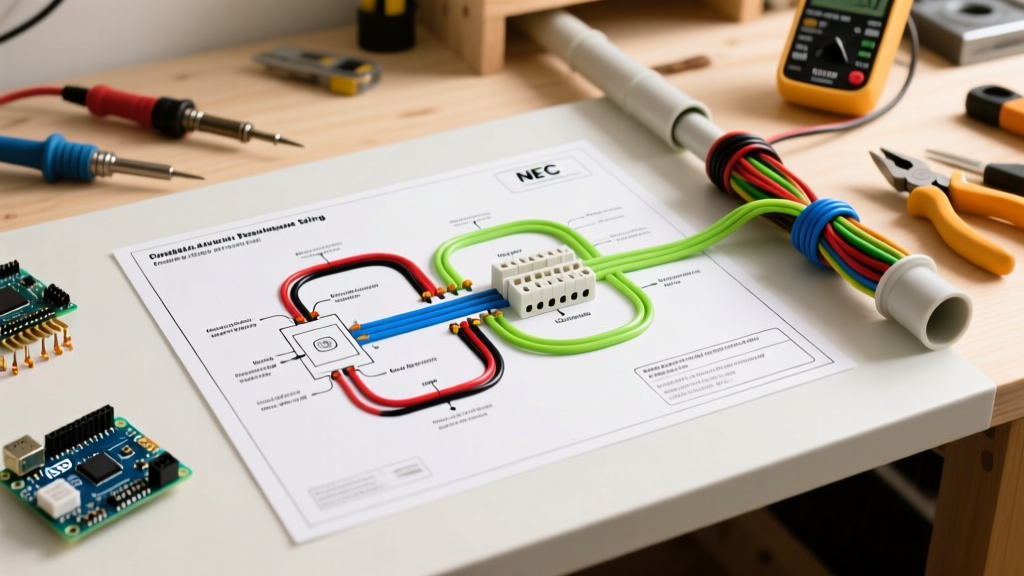
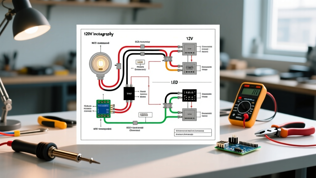
When reviewing electrical wiring diagrams for contactors, you will immediately notice a separation of lines. The power circuit flows vertically through the main poles, while the control circuit branches off horizontally.
- Power Terminals (L1/L2/L3 & T1/T2/T3): Line side (L) connects to the disconnect or breaker; Load side (T) connects directly to the motor or heater element.
- Coil Terminals (A1 & A2): The electromagnetic coil that pulls the main contacts closed. A1 is typically the hot control voltage, while A2 is the neutral or DC return.
- Auxiliary Contacts (NO/NC): Represented as 13/14 (Normally Open) or 21/22 (Normally Closed). These are used for holding circuits, PLC feedback, or interlocking.
Expert Insight: Never route high-amperage power wires and low-voltage control wires in the same conduit or wire duct. The electromagnetic interference (EMI) and harmonic noise generated by the power circuit during motor startup can induce phantom voltages in the control circuit, causing PLC input faults or erratic contactor chatter.
Wire Gauge Selection: Power vs. Control Circuits
Sizing wire for contactors requires adhering to NFPA 70 (National Electrical Code), specifically Article 430 for motors. The most critical rule is the 125% Continuous Load Rule. You must size the power conductors for 125% of the motor's Full Load Amps (FLA), not the contactor's maximum resistive rating.
Calculating Power Wire Gauge (Example: 15 HP Motor)
- Identify the motor FLA: A standard 15 HP, 460V 3-phase motor has an FLA of approximately 21 Amps.
- Apply the 125% multiplier: 21A × 1.25 = 26.25 Amps.
- Select the wire: According to NEC Table 310.16 (75°C column), 10 AWG THHN copper wire is rated for 35 Amps, making it the safe, code-compliant choice.
Sizing the Control Circuit Wire
The control circuit is governed by the coil's Volt-Ampere (VA) burden. A modern Schneider Electric TeSys F contactor (e.g., LC1F115) features an AC coil with an inrush of ~200 VA and a sealed holding current of ~15 VA. While the steady-state current is less than 1 Amp, NFPA 79 mandates a minimum of 14 AWG MTW (Machine Tool Wire) for control cabinet wiring to ensure mechanical durability and withstand short-circuit forces. If the control station is located more than 50 feet from the panel, you must upsize to 12 AWG to prevent voltage drop, which can cause the contactor coil to hum, overheat, and fail to pull in completely.
Contactor Sizing & Wire Gauge Matrix (460V 3-Phase)
| Motor HP | FLA (Amps) | Min. Power Wire (AWG) | Control Wire (AWG) | Lug Torque Spec |
|---|---|---|---|---|
| 5 HP | 7.6 A | 14 AWG | 14 AWG MTW | 1.2 Nm (M3.5) |
| 15 HP | 21.0 A | 10 AWG | 14 AWG MTW | 2.5 Nm (M4) |
| 50 HP | 65.0 A | 4 AWG | 14 AWG MTW | 6.0 Nm (M6) |
| 100 HP | 124.0 A | 1/0 AWG | 14 AWG MTW | 12.0 Nm (M8) |
NEMA vs. IEC Color Code Standards
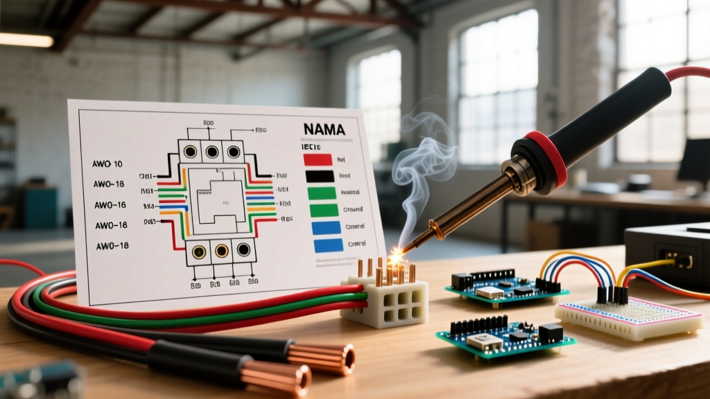
When building panels destined for global markets or strict local AHJ (Authority Having Jurisdiction) inspections, wire color coding is non-negotiable. North American NEMA standards (driven by NFPA 79) differ significantly from European IEC 60204-1 standards.
NFPA 79 (NEMA) Color Codes
- Black: 460V / 208V / 240V AC Power (Phase A, B, C typically Black, Red, Blue).
- Red: 120V AC Control circuits (internal to the panel).
- Blue: 24V DC Control circuits.
- Yellow: 120V AC Control circuits powered from an external source (interlocks).
- White / Gray: AC Neutral / DC Midpoint.
- Green w/ Yellow Stripe: Protective Earth (PE).
IEC 60204-1 Color Codes
- Brown, Black, Gray: 3-Phase AC Power (L1, L2, L3).
- Blue: AC Control circuits.
- Blue w/ White Stripe: DC Control circuits.
- Light Blue: AC Neutral.
- Green / Yellow: Protective Earth (PE).
Real-World Failure Modes: When Wiring Goes Wrong
Even with perfect electrical wiring diagrams for contactors, physical installation errors lead to catastrophic failures. Here are the most common edge cases we see in the field:
1. Thermal Creep on Power Lugs: Aluminum and copper expand at different rates. If you torque a 4 AWG copper wire into an aluminum contactor lug to the wrong spec, thermal cycling will cause the connection to loosen over 6-12 months. This increases resistance, leading to localized melting. Solution: Use modern contactors with EverLink terminal technology, which utilizes a spring-loaded mechanism to maintain constant torque despite thermal expansion.
2. Coil Burnout from Undersized Control Wires: If a 120V AC coil only receives 102V (a 15% drop) due to a long run of undersized 16 AWG wire, the magnetic field is too weak to fully seat the armature. The air gap remains, the coil draws continuous inrush current (which is 10x higher than sealed current), and the coil burns out within hours.
3. Auxiliary Contact Overloading: Wiring diagrams sometimes show PLC outputs driving contactor coils directly. A standard PLC transistor output sources only 0.5A. If the contactor coil requires 1.5A inrush, the PLC output will fry. Always use an interposing relay between the PLC and the main contactor coil.
Step-by-Step: Wiring a Schneider TeSys Giga Contactor
Let's apply this knowledge to wiring a premium Schneider Electric TeSys Giga contactor (LC1F265, priced around $850 in 2026) for a 150 HP HVAC compressor.
- Mount & Ground: Secure the contactor to the DIN rail or backpanel. Connect the PE (Green/Yellow) ground wire to the panel backpanel, not through the contactor.
- Terminate Power: Strip 3/4 inch of insulation from the 1/0 AWG THHN power wires. Insert into L1, L2, L3 and torque to 12.0 Nm using a calibrated torque screwdriver.
- Wire the Control Transformer: Connect the primary side of a 500VA control transformer to L1 and L2. Connect the secondary (120V AC) to the control fuse block.
- Terminate the Coil: Route 14 AWG Red MTW wire from the control fuse, through the overload relay's NC auxiliary contact (95/96), and into the contactor's A1 terminal. Connect A2 to the neutral bus.
- Auxiliary Feedback: Wire 14 AWG Blue MTW to terminals 13/14 (NO) to send a 'Motor Running' status signal back to the BMS (Building Management System) controller.
Frequently Asked Questions
Can I use DC wire color codes for AC control circuits?
No. Mixing blue (typically DC) and red (typically AC) in the same control cabinet violates NFPA 79 and creates severe safety hazards for technicians troubleshooting live panels. Always stick to Red for 120V AC and Blue for 24V DC.
Do I need to re-torque contactor terminals annually?
Legacy screw-clamp terminals require annual re-torquing due to thermal creep and vibration. However, modern spring-loaded or EverLink terminals (found on current-generation Eaton and Schneider models) are maintenance-free and explicitly exempt from annual retorque schedules under most IEC and NEMA guidelines.