
Understanding the Volvo TRW Electro-Hydraulic Power Steering (EHPS) System
When diagnosing or swapping steering components in modern vehicles, understanding the exact electrical architecture is critical. For Volvo platforms—specifically the P1 chassis (S40, V50, C30) and select P2 models—the steering system relies on an Electro-Hydraulic Power Steering (EHPS) pump rather than a traditional belt-driven hydraulic pump or a fully electric steering rack. Manufactured primarily by TRW, these pumps combine a 12V DC brushless motor with a hydraulic gear pump, controlled by an integrated Electronic Control Unit (ECU).
Because the motor must generate immense hydraulic pressure on demand, the electrical current draw is exceptionally high. Under heavy load conditions, such as lock-to-lock parking maneuvers, the pump can draw upwards of 85 amps. This extreme electrical demand makes the Volvo electric power steering pump wiring highly susceptible to thermal degradation, voltage drop, and connector corrosion if not maintained or repaired to exact Original Equipment (OE) specifications.
Common Failure Modes in the EHPS Wiring Harness
Before diving into the wiring diagram, it is essential to understand why these specific harnesses fail. The most frequent issues include:
- Connector Melting (Pin 1): The 3-pin OEM connector relies on standard blade terminals. Micro-corrosion increases electrical resistance. According to Joule's first law ($P = I^2R$), an 80A draw across even 0.05 ohms of corrosion generates significant heat, melting the plastic Sumitomo housing and causing an open circuit.
- Ground Point Bounce: The pump grounds to the chassis rail near the passenger wheel well. If this ground point corrodes or is painted over during bodywork, the ECU experiences "ground bounce," triggering a Central Electronic Module (CEM) fault code and disabling the pump to protect the vehicle's CAN bus network.
- Signal Wire Chafing: The 18 AWG data wire runs through tight looms near the subframe. Vibration and road debris frequently compromise the insulation, leading to CAN-Low shorts that illuminate the steering wheel warning light on the dash.
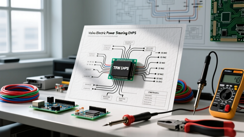
TRW EHPS Pump Pinout & Wiring Matrix
The standard Volvo P1/P2 TRW EHPS pump utilizes a sealed 3-pin connector. Below is the definitive pinout matrix, including required wire gauges based on the SAE J1128 Low Tension Primary Cable Standard for automotive high-current applications.
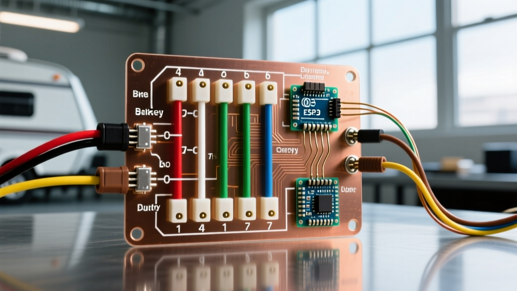
| Pin | Function | OE Wire Color (Typical) | Required Wire Gauge | Max Continuous Current |
|---|---|---|---|---|
| 1 | B+ 12V Main Power Feed | Red / Red-Black | 8 AWG (Minimum) | 85A (Peak Load) |
| 2 | Chassis Ground (GND) | Black / Brown | 8 AWG (Minimum) | 85A (Return Path) |
| 3 | CAN-Low / PWM Wake Signal | Green-White / Yellow | 18 - 20 AWG | < 500mA (Data) |
Critical Warning: Never attempt to jumper 12V power directly to Pin 3 to "force" the pump to turn on. Pin 3 is a low-voltage data link connected directly to the vehicle's High-Speed CAN network or the Steering Angle Sensor (SAS) module. Applying 12V to this pin will instantly destroy the pump's internal logic board, turning a $400 repair into a $1,200 replacement.
Custom Swap Engineering: Bypassing the CAN Bus for Kit Cars
A massive secondary market for the Volvo TRW EHPS pump exists in the kit car, hot rod, and off-road communities. Builders favor it because it eliminates the need for engine-driven hydraulic pumps, freeing up horsepower and allowing for flexible engine bay packaging. However, wiring this pump outside of a Volvo ecosystem requires engineering a dummy signal.
The PWM Signal Requirement
If you only connect Pin 1 (Power) and Pin 2 (Ground), the pump's internal ECU will detect a missing network signal. Depending on the exact TRW firmware version, the pump will either refuse to start, or it will default to a "fail-safe" mode. In fail-safe mode, the pump runs at maximum hydraulic pressure continuously. This causes severe whining, rapid fluid overheating, and continuous 60A+ current draws that will quickly drain a standard alternator.
To properly wire this pump for a custom build, you must provide a Pulse Width Modulation (PWM) signal to Pin 3. According to Hella's Automotive Electronics Technical Guides, variable assist steering systems require dynamic feedback to scale hydraulic pressure to vehicle speed.
Generating a Dummy PWM Signal
- Microcontroller Integration: Use an Arduino Nano or a dedicated 555-timer PWM generator circuit.
- Frequency Target: Set the PWM frequency to approximately 500Hz (standard for automotive CAN-Low simulation on these specific TRW units).
- Duty Cycle Mapping: Wire a potentiometer to your circuit to manually adjust the duty cycle between 10% (low pressure/highway driving) and 90% (high pressure/parking).
- Opto-isolation: Always use an opto-isolator or a logic-level MOSFET between your microcontroller and Pin 3 to protect your low-voltage electronics from the pump's massive inductive kickback when the motor cycles off.
Step-by-Step OEM Wiring Harness Repair
If you are repairing a melted pigtail on an intact Volvo S40, V50, or C30, follow this precise procedure to ensure long-term reliability. You can source OEM replacement pigtails and connectors through specialized suppliers like the FCP Euro Volvo Parts Catalog or authorized Volvo dealerships.
Phase 1: Preparation and Removal
- CEM Sleep Mode: Disconnect the negative battery terminal and wait exactly 15 minutes. This allows the Central Electronic Module (CEM) to enter sleep mode and safely power down the CAN bus network.
- Excise the Damage: Cut the damaged OEM connector off the harness at least 4 inches behind the melted plastic. Do not attempt to salvage terminals that have been subjected to high heat, as the copper loses its temper and spring tension.
- Strip and Clean: Strip 3/8" of insulation from the 8 AWG power and ground wires. Use isopropyl alcohol to clean any green copper oxide (verdigris) from the strands. If the oxidation extends too far up the loom, you must replace the entire harness run back to the B+ junction box.
Phase 2: Crimping and Sealing
- Terminal Crimping: Use an OEM Sumitomo 090 series or TE Connectivity DEUTSCH DT series sealed connector kit. Use a ratcheting crimper specifically calibrated for 8 AWG non-insulated terminals. A proper crimp should yield a pull-test strength of over 70 lbs.
- Adhesive Heat Shrink: Slide 3:1 shrink ratio, adhesive-lined marine heat shrink over the 8 AWG crimps. Apply heat until the adhesive purges from the ends, creating a watertight seal against road salt and moisture.
- Solder the Data Line: For the 18 AWG Pin 3 signal wire, crimp the terminal, but also apply a small amount of rosin-core solder to the wire barrel. Low-current data lines are highly susceptible to micro-vibrations; soldering prevents strand fatigue and intermittent CAN bus drops.
Diagnostic Flowchart for Steering Faults
When faced with a "Steering Wheel Warning" message or heavy steering, do not immediately condemn the pump. Use a digital multimeter (DMM) to perform this voltage drop and signal verification sequence:
- Step 1: Static Voltage Check. With the ignition ON (engine OFF), measure voltage between Pin 1 and the battery negative post. It should read within 0.1V of battery voltage (approx. 12.4V). If it reads 0V, check the 40A/60A maxi-fuse in the engine bay B+ relay box.
- Step 2: Dynamic Voltage Drop Test. Connect your DMM positive lead to the battery positive post, and the negative lead to Pin 1 (back-probed). Start the engine and have an assistant turn the steering wheel lock-to-lock. The DMM should read less than 0.2V. A reading above 0.5V indicates high resistance in the power feed wire or a corroded B+ junction block.
- Step 3: Ground Integrity Test. Move the DMM positive lead to Pin 2 and the negative lead to the battery negative post. Perform the lock-to-lock test again. Voltage drop must remain under 0.2V. If higher, remove the chassis ground bolt, sand the paint to bare metal, apply dielectric grease, and re-torque to 25 Nm.
- Step 4: CAN Bus Oscilloscope Check. If power and ground are perfect, back-probe Pin 3. Using an oscilloscope or a CAN bus analyzer, verify that a square-wave data signal is present when the ignition is turned on. A flat 0V or static 12V line indicates a broken wire between the CEM/SAS module and the pump.
Essential Tools & Material Specifications
To execute these repairs to a professional standard, the following tools are mandatory:
| Tool / Material | Specification / Part Number | Purpose |
|---|---|---|
| Ratcheting Crimper | TE Connectivity UDAR or IWISS SN-58B | Ensures gas-tight crimps on 8 AWG terminals |
| Heat Shrink Tubing | 3M MDT, 3:1 Ratio, Adhesive-Lined | Waterproof sealing for high-current joints |
| Digital Multimeter | Fluke 87V (True RMS) | Accurate voltage drop and resistance testing |
| Dielectric Grease | Permatex 22058 | Prevents galvanic corrosion on ground points |
Summary
Mastering Volvo electric power steering pump wiring requires respecting the immense electrical forces at play. Whether you are restoring a corroded OEM harness on a 2007 V50 or engineering a PWM bypass for a custom track car, adhering to strict wire gauge requirements, utilizing sealed automotive connectors, and understanding the CAN bus wake-up signal are the keys to a reliable, whine-free steering system. Always prioritize voltage drop testing over visual inspections, as the most dangerous electrical faults in high-amperage steering systems are entirely invisible to the naked eye.