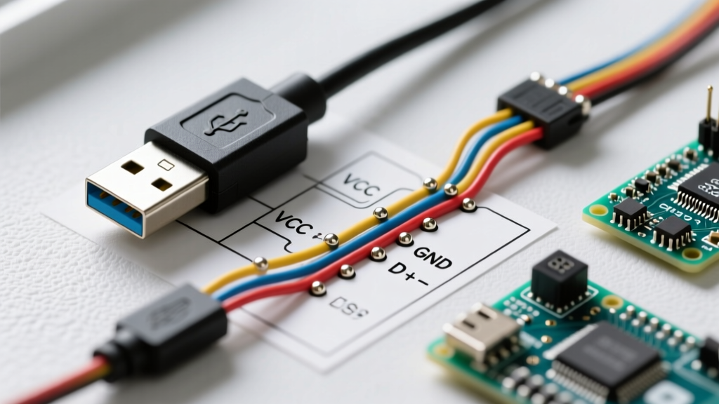

Integrating USB Power and Data in Custom Appliances
As smart appliances and custom DIY workbench tools increasingly rely on low-voltage DC power and serial data communication, understanding the exact wiring diagram for a USB cable is no longer just for IT professionals. For electrical DIYers, appliance repair technicians, and custom control panel builders, properly wiring USB-A and USB-C interfaces is critical for powering microcontrollers, running diagnostic data lines, and even driving low-wattage PTC heating elements. In 2026, with the widespread adoption of USB-C Power Delivery (PD) 3.1 supporting up to 240W, USB cables are actively replacing traditional barrel jacks and proprietary AC-DC adapters in modern appliance design.
This guide provides an expert-level breakdown of USB cable pinouts, wire gauge selection for high-current appliance tethers, and the specific pull-down resistor configurations required to ensure your custom appliance successfully negotiates power from a USB-C source.
Standard USB Type-A Wiring Diagram and Pinout
The standard USB 2.0 Type-A cable remains the backbone for legacy appliance control boards, diagnostic ports, and low-power (up to 12W) sensor arrays. A standard USB-A cable contains four shielded wires and an overall braided shield with a drain wire.
| Pin | Wire Color | Function | Voltage / Signal | Appliance Application |
|---|---|---|---|---|
| 1 | Red | VBUS (Power) | +5V DC (±5%) | Powering 5V relays, logic ICs, and LED indicators |
| 2 | White | D- (Data) | Differential Data | Serial communication to appliance MCU (e.g., ESP32) |
| 3 | Green | D+ (Data) | Differential Data | Serial communication to appliance MCU |
| 4 | Black | GND (Ground) | 0V Reference | Common ground for appliance logic circuits |
| Shell | Bare / Uninsulated | Shield / Drain | Chassis Ground | EMI shielding against appliance motor noise |
The Wire Gauge Trap in Appliance Tethers
Commercial USB cables typically use 28 AWG for data lines and 24 AWG for power (VBUS/GND). While sufficient for a 1-meter phone charger, 24 AWG is a massive failure point in DIY appliance wiring where cable runs exceed 2 meters. According to the USB Implementers Forum (USB-IF) specifications, the voltage at the device end must not drop below 4.75V.
Real-World Calculation: A 24 AWG copper wire has a resistance of roughly 84 mΩ per meter. In a 3-meter appliance tether, the round-trip resistance for VBUS and GND is 6 meters × 0.084Ω = 0.504Ω. If your appliance control board draws 2A, the voltage drop is 1.008V. Your 5V source will deliver only 3.99V to the board, causing brownouts and MCU resets. Solution: Always strip the outer jacket of commercial cables and replace the VBUS and GND lines with 20 AWG silicone wire for custom appliance builds exceeding 1.5 meters.
USB-C Power Delivery (PD) for High-Wattage Appliances
For modern DIY appliances—such as portable 12V compressor fridges, 20V PTC ceramic heaters, or smart HVAC diagnostic tools—USB-C is the standard. However, simply wiring VBUS and GND on a USB-C receptacle will result in zero power output. USB-C sources require a specific configuration on the Configuration Channel (CC) pins before enabling VBUS.
Critical USB-C Pins for Appliance Sinks (UFP)
- A4, B9, A9, B4 (VBUS): Power delivery lines. Must be rated for 5A (use 18 AWG wire for 100W+ applications).
- A1, B12, A12, B1 (GND): Ground return paths.
- A5 (CC1) and B5 (CC2): The Configuration Channels. This is where most DIY appliance builds fail.
Expert Warning: To draw 5V from a USB-C port, your appliance PCB must have 5.1kΩ pull-down resistors connecting both CC1 and CC2 to GND. Without these resistors, the source port will not recognize the appliance, and VBUS will remain disabled. For negotiating higher voltages (9V, 12V, 20V) to drive appliance motors or heaters, you must integrate a PD sink controller IC, such as the STMicroelectronics STUSB4500 or Texas Instruments TPS65987D, which dynamically alters the CC line resistance to request specific power profiles. For deeper architectural guidance, refer to the Texas Instruments USB-C Design Overview.
Step-by-Step: Splicing a USB Cable for an Appliance Control Board
When integrating a USB tether directly into an appliance chassis or splicing a cable for a custom control panel, follow this rigorous soldering and shielding procedure to ensure compliance with safety standards like UL 62368-1 for ICT and appliance equipment.
- Jacket Stripping: Remove 40mm of the outer PVC jacket using a precision wire stripper. Do not nick the inner braided shield.
- Shield Preparation: Unbraid the copper shield and twist it together with the bare drain wire. This combined shield wire is critical for mitigating Electromagnetic Interference (EMI) generated by appliance inverters and brushless DC motors.
- Data Line Protection: Slip 3:1 ratio adhesive-lined heat shrink (e.g., 3M EPS300) over the White (D-) and Green (D+) wires. These wires must remain as a twisted pair. Do not untwist them more than 5mm from the termination point to maintain the 90-ohm differential impedance.
- Soldering: Tin the wires using 63/37 Sn/Pb rosin-core solder at 320°C, or SAC305 lead-free solder at 360°C. For appliance PCBs with heavy ground planes, preheat the board to 100°C to prevent cold solder joints caused by rapid heat dissipation.
- Shield Grounding: Solder the twisted shield/drain wire to the appliance chassis ground or the USB receptacle shell. Never connect the shield to the logic GND on the PCB side if the appliance has a switching power supply, as this will inject high-frequency switching noise directly into your MCU's ground reference.
Common Failure Modes in Appliance USB Wiring
1. EMI-Induced Data Corruption
Appliances with inductive loads (e.g., HVAC blower motors, washing machine drain pumps) generate massive voltage spikes and EMI. If your USB data lines are unshielded or routed parallel to AC mains wiring inside the appliance chassis, the D+/D- differential signals will experience common-mode noise, resulting in USB enumeration failures. Fix: Route USB cables at a 90-degree angle to AC lines and install a common-mode choke (e.g., TDK ACM2012-900-2P) on the D+/D- lines at the PCB entry point.
2. USB-C Intermittent Disconnects
If an appliance vibrates (like a compressor or a motorized standing desk), standard USB-C friction fits will fail. The USB-C specification allows for a specific insertion/extraction force profile, but vibration causes micro-disconnects on the CC pins, forcing the PD controller to reset and drop VBUS. Fix: Use USB-C receptacles with extended shell retention tabs and secure the cable strain relief to the appliance chassis using a 3D-printed TPU clamp or a metal cable gland rated for IP65 if the appliance operates in damp environments.
3. Ground Loops in Diagnostic Tethers
When connecting a laptop to an appliance's internal USB diagnostic port while the appliance is also grounded to the AC mains via its power cord, a ground loop can occur if the laptop is plugged into a different AC circuit. This can fry the appliance's MCU. Fix: Implement digital isolators (e.g., Analog Devices ADuM1201) on the D+/D- lines between the USB port and the appliance's internal microcontroller to break the galvanic ground connection while preserving data integrity.
Summary of Best Practices
Mastering the wiring diagram for a USB cable in the context of appliance modification requires moving beyond simple color-matching. It demands an understanding of voltage drop physics, USB-C CC pin negotiation logic, and rigorous EMI shielding techniques. By specifying 20 AWG wire for high-current VBUS lines, implementing mandatory 5.1kΩ pull-down resistors for USB-C sinks, and properly terminating braided shields to chassis ground, you ensure your DIY appliance integrations are robust, safe, and compliant with modern electrical standards.