
Why Your Fuel Pump Demands a Dedicated Relay Circuit
Modern electronic fuel injection (EFI) systems rely on high-flow, in-tank, or inline fuel pumps to maintain strict rail pressures. Whether you are wiring a standard Walbro 255 LPH (liters per hour) pump or a high-demand DeatschTek DW300c, these components draw significant continuous current—often between 15A and 20A under load, with initial inrush spikes exceeding 25A. Attempting to route this current directly through an engine control unit (ECU) driver, a factory inertia switch, or a standard dashboard toggle switch will result in melted insulation, severe voltage drop, and catastrophic module failure.
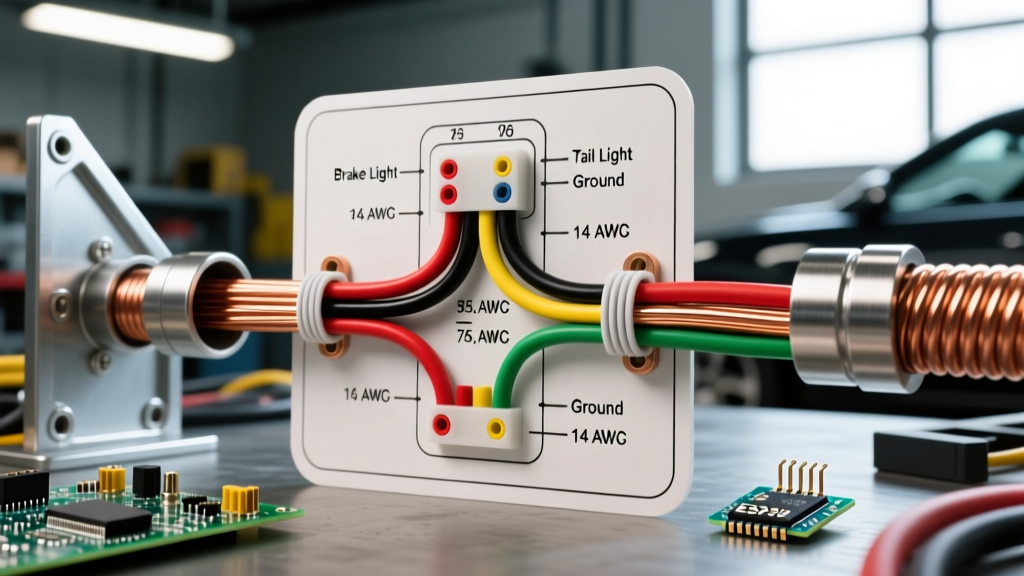
This is where understanding the wiring diagram for fuel pump relay configurations becomes critical. A relay acts as a heavy-duty, remote-controlled electrical switch. It allows a low-current trigger signal (typically 1A or less from your ECU or ignition switch) to safely control a high-current power circuit directly from the battery. In this comprehensive guide, we will dissect the standard ISO automotive relay, map out the exact wiring topology, and provide actionable engineering data to ensure your fuel delivery system operates flawlessly.
Decoding the Standard ISO Relay Pinout
Before grabbing a spool of wire, you must understand the anatomy of the component you are working with. The vast majority of automotive fuel pump applications utilize a standard 4-pin or 5-pin ISO Mini Relay (such as the ubiquitous Bosch 0332014150 or equivalent 30A/40A models from Littelfuse and Tyco). These relays feature standardized DIN 72552 terminal numbers stamped directly into the plastic housing or printed on the integrated schematic.
The Critical Pin Assignments
- Pin 30 (Common / Power Input): This is your high-current feed from the battery. It is constantly hot and should be protected by an appropriately sized inline fuse.
- Pin 87 (Normally Open / Power Output): This pin connects to the positive terminal of your fuel pump. When the relay coil is energized, the internal contactor bridges Pin 30 to Pin 87, delivering full battery voltage to the pump.
- Pin 86 (Coil Power / Trigger Input): This receives the low-current 12V signal from your ignition switch, ECU fuel pump driver, or oil pressure safety switch.
- Pin 85 (Coil Ground): This completes the low-current control circuit by grounding the relay's internal electromagnetic coil.
- Pin 87a (Normally Closed): Present only on 5-pin relays. This pin is connected to Pin 30 when the relay is off. Do not use Pin 87a for fuel pump wiring. Leaving it connected or miswiring it can cause the pump to run continuously when the vehicle is off, or create a dead short if improperly grounded.
Expert Tip: Always purchase relays with an integrated internal suppression resistor or diode. If your relay lacks internal protection, you must solder an external flyback diode (like a 1N4004) across pins 85 and 86 to prevent inductive kickback from frying your ECU's solid-state driver when the relay shuts off. For an in-depth look at relay switching physics, refer to this comprehensive guide on relay switch circuits.
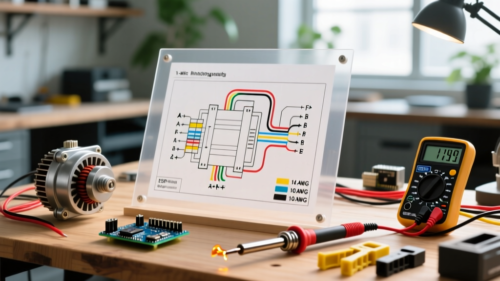
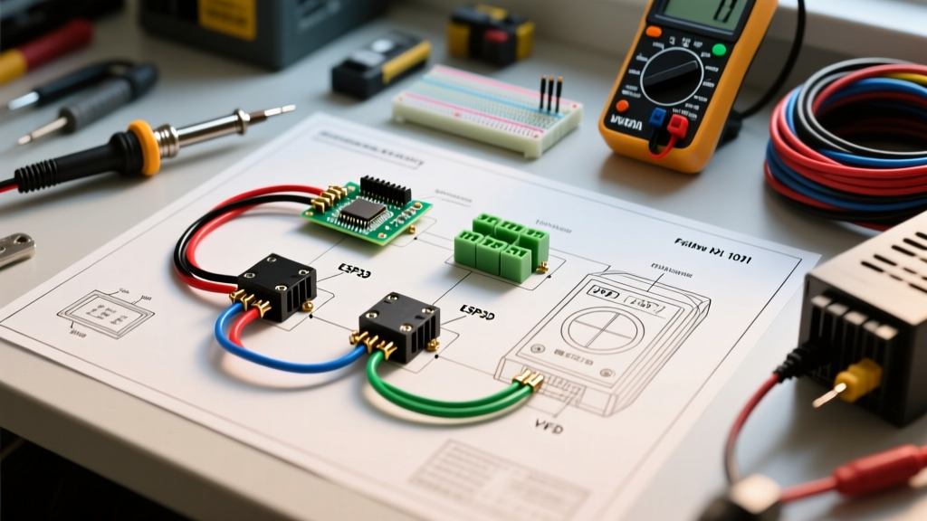
Visualizing the Wiring Diagram for Fuel Pump Relay Systems
While visual schematics are helpful, understanding the logical flow of the current is what separates amateurs from professionals. Below is the step-by-step electrical topology for a robust, fail-safe fuel pump relay circuit.
1. The High-Current Power Circuit (Load Side)
- Route a primary power wire directly from the vehicle's main battery positive terminal (or a high-amperage distribution busbar).
- Install an inline ATC/ATO blade fuse holder within 18 inches of the battery connection. For a 15A continuous draw pump, use a 20A fuse to accommodate inrush current without nuisance blowing.
- Connect the other end of this fused wire to Pin 30 on the relay.
- Run a second wire from Pin 87 directly to the positive terminal of the fuel pump (or the factory EFI fuel pump harness plug).
- Ensure the fuel pump's negative terminal is grounded to a clean, bare-metal chassis point using a dedicated ground strap.
2. The Low-Current Control Circuit (Trigger Side)
- Run a wire from your ECU's fuel pump trigger pin (or an ignition-switched 12V source) to Pin 86.
- Run a wire from Pin 85 to a clean chassis ground.
- Optional but recommended: Wire a 1N4004 diode in parallel across Pins 86 and 85, with the diode's cathode (the silver stripe) pointing toward Pin 86. This clamps the reverse voltage spike generated when the coil's magnetic field collapses.
Wire Gauge and Component Selection Matrix
Using undersized wire for a fuel pump is a fire hazard and causes severe voltage drop, which directly reduces fuel pump flow rate and pressure. According to standard AWG current capacity guidelines, you must account for both the continuous amperage and the physical length of the wire run. Always use automotive-grade cross-linked wire (TXL, GXL, or SXL) rather than standard PVC wire, as it withstands under-hood temperatures and resists chemical degradation from fuel spills.
| Circuit Section | Recommended AWG (TXL/GXL) | Max Continuous Current | Application Notes |
|---|---|---|---|
| Battery to Fuse to Pin 30 | 10 AWG | 30A - 40A | Handles inrush spikes; minimizes voltage drop over long engine bay runs. |
| Pin 87 to Fuel Pump (+) | 12 AWG | 20A - 25A | Sufficient for most 255-340 LPH pumps. Use 10 AWG for dual-pump setups. |
| Fuel Pump to Chassis (-) | 12 AWG | 20A - 25A | Ground wire must match or exceed the positive wire gauge. |
| Ignition/ECU to Pin 86 | 16 AWG or 18 AWG | 3A - 5A | Relay coil draws less than 150mA; 18 AWG is perfectly safe and flexible. |
| Pin 85 to Chassis (-) | 16 AWG or 18 AWG | 3A - 5A | Keep this ground as short as possible to ensure immediate relay actuation. |
Step-by-Step Installation and Termination Protocol
A flawless wiring diagram for a fuel pump relay is useless if the physical terminations are compromised. Vibration and moisture are the enemies of automotive electrical systems. Follow this strict termination protocol:
- Ditch the Twist-and-Tape Method: Never use electrical tape or standard twist-on wire nuts under the hood. They will unravel and absorb moisture.
- Use Adhesive-Lined Heat Shrink: For any splices, use marine-grade, adhesive-lined polyolefin heat shrink tubing. When heated, the inner meltable adhesive seals out water and prevents capillary action from drawing moisture into the copper strands.
- Crimp vs. Solder: For relay pigtail connectors, use open-barrel or closed-barrel crimps with a proper ratcheting crimper (like the IWISS SN-28B). If you choose to solder the relay pigtail wires, you must use a heat sink (like a hemostat clamped between the solder joint and the relay pin) to prevent melting the relay's internal plastic housing.
- Relay Mounting: Mount the relay vertically with the pins pointing downward. This ensures that any condensation or water ingress drips away from the internal contactor and coil. You can source high-quality sealed automotive relays and sockets from major electronic distributors to ensure weather resistance.
Diagnosing Edge Cases and Failure Modes
Even with a perfect wiring diagram for your fuel pump relay, components degrade. Here is how to diagnose the most common failure modes using a digital multimeter (DMM) like a Fluke 87V.
1. The 'Clicking' Relay but Dead Pump
If you hear the relay click but the pump doesn't prime, the coil is functioning, but the high-current contacts are likely burnt or pitted. Test: Set your DMM to DC Volts. Back-probe Pin 87 with the relay energized. If you read 12.6V at Pin 87 but 0V at the pump connector, you have an open circuit in the output wire. If you read 8V at Pin 87 while the pump is trying to run, the internal relay contacts have high resistance and the relay must be replaced.
2. Voltage Drop Testing
A healthy relay circuit should exhibit minimal voltage drop. Test: Set your DMM to DC Volts. Place the red probe on the battery positive and the black probe on Pin 30 while the pump is running. A reading above 0.1V indicates excessive resistance in the supply wire or a corroded fuse holder. Repeat from Pin 87 to the pump positive terminal.
3. Parasitic Draw from Miswired Coils
If your battery dies overnight, the relay coil might be back-feeding through the ECU driver. Ensure your trigger wire (Pin 86) is genuinely switching 12V, and that Pin 85 is going to a hard ground, not a switched ground, unless specifically dictated by a factory ECU logic map.
Frequently Asked Questions
Can I use a 40A relay for a fuel pump that only draws 12A?
Yes. A relay's amperage rating indicates the maximum current its internal contacts can safely handle before arcing or melting. Using a 40A relay for a 12A pump provides a massive safety margin and increases the lifespan of the relay. Just ensure your inline fuse is sized to protect the wire and the pump (e.g., a 15A or 20A fuse), not the relay.
Why does my ECU fuel pump driver keep burning out?
This is almost always caused by inductive kickback. When the ECU cuts power to the relay coil (Pin 86), the collapsing magnetic field generates a high-voltage reverse spike (often exceeding 100V). Without a flyback diode across the coil pins, this spike travels back into the ECU's solid-state transistor, destroying it. Always use a diode or a relay with an integrated suppression resistor.
Should I wire the relay trigger to the ignition switch or the ECU?
In modern EFI builds, the ECU should always control the relay. The ECU will prime the pump for 2-3 seconds when the key is turned to the 'ON' position (to build rail pressure) and will cut power instantly if the engine stalls or oil pressure drops. Wiring directly to an ignition switch bypasses these critical safety and priming protocols.