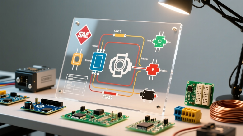

The Evolution of Motor Wiring: From 12V Cranks to 800V Traction
Understanding auto electrical wiring diagram symbols is no longer just about tracing a simple 12-volt starter motor circuit. As the automotive industry has shifted toward electrification, the complexity of motor wiring has expanded exponentially. In 2026, a modern technician or DIY enthusiast must be fluent in both traditional Internal Combustion Engine (ICE) starter circuits and high-voltage Electric Vehicle (EV) traction motor architectures. Whether you are troubleshooting a Bosch-type starter solenoid on a diesel truck or diagnosing a 3-phase AC traction motor on an 800V platform like the Hyundai E-GMP, the diagram is your only reliable map.
This comprehensive tutorial decodes the essential auto electrical wiring diagram symbols specific to motor applications, bridging the gap between legacy SAE standards and modern high-voltage ISO requirements.
Foundational Standards: SAE, ISO, and DIN 72552
Before interpreting specific graphical symbols, you must understand the governing nomenclature. Automotive wiring diagrams rely on a mix of graphical representations and alphanumeric terminal designations. The most critical standard for terminal identification is DIN 72552, which assigns specific numbers to electrical connections to ensure universal understanding across manufacturers.
- Terminal 30: Direct connection to the battery positive (B+). Always hot.
- Terminal 15: Switched positive via the ignition switch. Hot only in 'Run' and 'Start'.
- Terminal 31: Direct ground connection to the chassis or battery negative.
- Terminal 50: Starter motor control circuit (direct from ignition switch to starter solenoid).
For wire insulation and gauge standards, North American vehicles heavily reference SAE International specifications, while global platforms utilize ISO standards. For instance, ISO 6722-1 dictates the dimensional and insulation requirements for single-core cables used in road vehicles, which directly influences how wire thickness and shielding are depicted in schematic legends.
Expert Callout: Wire Gauge DepictionIn most auto electrical wiring diagram symbols, wire gauge is not drawn to scale graphically. Instead, it is denoted by a numerical label intersecting the wire line (e.g., '4.0' for 4 mm² or '4 AWG'). When wiring a high-torque starter motor, never substitute the specified 4 AWG or 2 AWG cable with a smaller gauge, or you will induce severe voltage drop during the high-amperage cranking phase (often exceeding 250A).
Master Symbol Matrix for Automotive Motor Circuits
Below is a targeted reference table for the most common auto electrical wiring diagram symbols encountered when working with both ICE and EV motor systems.
| Component | Symbol Description | Standard / Ref | Real-World Motor Application |
|---|---|---|---|
| DC Starter Motor | Circle with an 'M' and a starter bendix gear icon on the shaft | SAE J1292 | Denso 1.4kW PMGR starter on Toyota 2.7L engines |
| Starter Solenoid | Rectangle adjacent to the motor circle, with a dashed mechanical link line | DIN 72552 (Term 30/50) | Delco Remy 39MT heavy-duty solenoid |
| 3-Phase AC Motor | Circle with an 'M', '3~', and three protruding lines (U, V, W) | ISO 80000-6 | Tesla Model 3 Rear Drive Unit (Induction/SyncRel) |
| Motor Resolver | Circle containing overlapping sine and cosine waveforms | OEM Specific | Rotor position feedback for SiC inverter commutation |
| HV Interlock Loop (HVIL) | Dashed line encircling high-voltage components with a continuity loop symbol | SAE J2344 | Safety shutdown circuit for 800V traction inverters |
Step-by-Step: Tracing a Traditional ICE Starter Motor
Let us apply these symbols to trace a standard starter motor circuit. This exercise is critical for diagnosing 'no-crank' conditions.
- Locate Terminal 30 (B+): Find the heavy-gauge wire symbol (usually labeled 4 AWG or 50 mm²) originating from the battery positive symbol. This line travels directly to the starter solenoid's main stud (Terminal 30).
- Trace the Control Circuit (Terminal 50): Identify the ignition switch symbol. A lighter gauge wire (typically 12 AWG or 2.5 mm²) leaves the 'Start' position of the switch. In many modern diagrams, this wire routes through a starter relay or the Powertrain Control Module (PCM) before reaching Terminal 50 on the solenoid.
- Verify the Ground Path (Terminal 31): The motor circle will have a ground symbol attached to its casing. In reality, this is the physical mounting point of the starter to the engine block. If the diagram shows a dedicated ground wire, trace it to the chassis ground node.
- Check for Immobilizer Interlocks: Modern diagrams will show a logic gate or relay coil symbol in the Terminal 50 path, controlled by the Body Control Module (BCM). If the transponder key is unrecognized, the BCM keeps this relay open, breaking the circuit.
Advanced EV Traction Motor Symbolism (2026 Architectures)
The shift to electric vehicles has introduced entirely new categories of auto electrical wiring diagram symbols. According to data from the Alternative Fuels Data Center, the proliferation of EVs requires technicians to understand high-voltage 3-phase systems, which operate fundamentally differently from 12V DC circuits.
Inverter and Phase Symbols
In an EV wiring diagram, the traction motor is rarely shown in isolation. It is depicted as part of an integrated Drive Unit (e-Axle). The symbol for the inverter is typically a large rectangle bridging the high-voltage DC bus (often denoted by thick, orange-shaded lines representing 400V to 800V DC) and the 3-phase AC output. The three output phases are labeled U, V, and W. When diagnosing a motor that shudders or fails to spin, technicians use these schematic labels to perform phase-to-phase resistance tests with a milliohm meter, ensuring the hairpin stator windings have not shorted.
Resolver and Temperature Sensors
Unlike a simple DC starter, an AC traction motor requires precise rotor positioning to commutate the magnetic field. The diagram will feature a resolver symbol (a circle with sine/cosine waves) connected to the inverter via a shielded twisted-pair cable. Additionally, you will see NTC (Negative Temperature Coefficient) thermistor symbols embedded within the motor stator windings. If the diagram shows these thermistors wired in series, a single open circuit in the sensor loop will cause the inverter to derate power or shut down entirely to prevent thermal destruction of the motor.
Diagnostic Edge Cases: When the Diagram Lies
Schematics represent ideal conditions. As an expert, you must account for real-world physical degradation that symbols cannot convey.
Critical Warning: The Hidden Voltage Drop
A wiring diagram shows a solid line connecting the battery to the starter motor, implying zero resistance. In reality, corrosion on the chassis ground strap or a loose crimp on the 4 AWG positive cable can introduce 0.5 ohms of resistance. During a 200A crank event, Ohm's Law (V = I x R) dictates a 100-volt drop, leaving only 2 volts at the starter. Always perform a live voltage drop test across the physical cable, rather than just checking for continuity with a multimeter.
Another common discrepancy involves HVIL (High Voltage Interlock Loop) circuits in EVs. The diagram will show a simple low-voltage (usually 5V or 12V) loop passing through the high-voltage connector symbols. However, these connectors utilize microscopic pilot pins that make contact only when the connector is fully seated. A diagram will not show you that a slightly bent pilot pin, or a connector pushed in only 90% of the way, will open the HVIL circuit, instantly commanding the main contactors to open and disabling the traction motor.
Frequently Asked Questions
What does a dashed line between two symbols mean in an auto motor diagram?
A dashed line typically represents a mechanical linkage rather than an electrical connection. For example, in a starter motor diagram, a dashed line connects the solenoid coil symbol to the heavy-duty contact switch symbol, indicating that the magnetic field physically pulls the plunger to close the high-amperage contacts. In EV diagrams, dashed lines may also denote shielding or physical housing boundaries.
How are wire colors represented in these schematics?
Wire colors are usually indicated by a two-letter code intersecting the wire line (e.g., 'BK' for Black, 'RD/WH' for Red with a White tracer). In modern digital OEM diagrams (like those accessed via Mitchell1 or Alldata), the wire line itself is color-coded on the screen, but you must always verify using the alphanumeric legend, as printouts or grayscale screens can lead to misidentification.
Why do some motor diagrams show a diode across the relay coil?
This is a flyback (or snubber) diode. When the ignition switch cuts power to the starter relay coil, the collapsing magnetic field generates a high-voltage reverse spike. The diode symbol, placed in reverse bias across the coil, provides a safe path for this spike to dissipate, protecting the PCM's solid-state driver transistors from catastrophic failure.