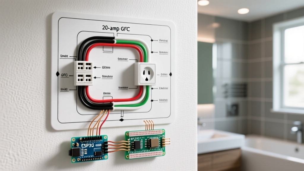

Understanding the Standard Wiring Diagram for a Bathroom
Designing and executing a safe electrical layout in a high-moisture environment requires strict adherence to modern safety codes. When you examine a standard wiring diagram for a bathroom, you are not just looking at a map of wires; you are looking at a life-safety system engineered to prevent electrocution and electrical fires. In 2026, with the widespread adoption of the 2023 National Electrical Code (NEC) and early municipal enforcements of upcoming revisions, the baseline for bathroom wiring mandates dedicated 20-amp circuits, Tamper-Resistant (TR) Ground Fault Circuit Interrupter (GFCI) protection, and precise spatial placement of receptacles.
This comprehensive guide breaks down the conceptual wiring diagram for a modern bathroom, translating schematic lines into actionable, code-compliant physical installations. Whether you are wiring a new primary suite or upgrading a 1980s guest bath, understanding the topology of line, load, neutral, and ground pathways is critical.
Core Circuit Topology: The 20-Amp Dedicated Receptacle Circuit
At the heart of every bathroom wiring diagram is the 20-amp receptacle circuit. According to NFPA National Electrical Code Section 210.11(C)(3), at least one 120-volt, 20-ampere branch circuit must be provided to supply bathroom receptacle outlets. This circuit must have no other outlets, meaning it cannot power lighting, exhaust fans, or outlets in adjacent rooms, with one specific exception (detailed in the MWBC section below).
Wire Gauge and Breaker Sizing Matrix
Selecting the correct cable and overcurrent protection is non-negotiable. Below is the standard matrix for bathroom branch circuits based on current NEC guidelines and 2026 material pricing.
| Circuit Type | Breaker Size | Wire Gauge (NM-B) | Approx. 250ft Roll Cost (2026) | Application |
|---|---|---|---|---|
| Bathroom Receptacles | 20-Amp Single Pole | 12/2 AWG Copper | $115 - $140 | GFCI outlets, vanity outlets |
| Bathroom Lighting/Fan | 15-Amp Single Pole | 14/2 AWG Copper | $75 - $95 | Vanity lights, exhaust fans |
| Heated Floors (Radiant) | 20-Amp Single Pole | 12/2 AWG Copper | $115 - $140 | Dedicated thermostat and mats |
| Jetted Tub Motor | 20-Amp Single Pole | 12/2 AWG Copper | $115 - $140 | Dedicated GFCI protected motor |
Step-by-Step Flow: Wiring the GFCI Receptacle
The most complex node in your bathroom wiring diagram is the GFCI receptacle. Modern diagrams utilize a 'Line and Load' configuration to protect downstream standard receptacles. Here is the precise sequence for wiring a 20-Amp TR GFCI (such as the Leviton GFTR2-20W, typically retailing around $24-$28).
- Identify Line vs. Load: Use a non-contact voltage tester and a multimeter to identify the incoming power (Line) and the cable heading to the next outlet (Load). Mark the Line cable with black electrical tape.
- Strip and Prep: Strip exactly 5/8 inch of insulation from the 12 AWG conductors. Do not score the copper, as this creates micro-fractures that lead to arcing.
- Terminate Ground: Connect the bare copper ground wires using a wire nut and a 6-inch green pigtail to the GFCI's green ground screw.
- Terminate Neutrals: Connect the incoming white neutral to the 'LINE' terminal marked WHITE. Connect the downstream white neutral to the 'LOAD' terminal marked WHITE.
- Terminate Hots: Connect the incoming black hot to the 'LINE' terminal marked BLACK (usually the brass screw). Connect the downstream black hot to the 'LOAD' terminal marked BLACK.
- Apply Calibrated Torque: NEC 110.14(D) requires that terminal screws be tightened to the manufacturer's specified torque. Use an insulated torque screwdriver set to 14 in-lbs (standard for most 20A Leviton/Hubbell GFCIs) to prevent loose connections and subsequent thermal melting.
Pro-Tip on Spatial Placement: NEC 210.52(D) mandates that at least one receptacle must be located within 36 inches of the outside edge of the sink basin. Furthermore, receptacles cannot be installed face-up in countertop surfaces or within the 'wet zone' of a shower/tub area.
Integrating Lighting and Exhaust Fans
While receptacles require a dedicated 20-amp circuit, lighting and exhaust fans can be wired on a separate 15-amp or 20-amp circuit. In many modern wiring diagrams for a bathroom, a single 14/2 or 12/2 cable is run from the panel to a multi-gang switch box, which then distributes power to the vanity lights and the exhaust fan.
Switch Loop vs. Direct Feed
If you are installing a combination fan/light unit (like the Broan-NuTone Roomside Series), you will need independent control. A standard wiring diagram for this scenario utilizes a 14/3 NM-B cable run from the switch box to the fan housing.
- White Wire: Serves as the constant neutral (spliced in the switch box and terminated at the fan).
- Black Wire: Switched hot for the fan motor.
- Red Wire: Switched hot for the LED light array.
- Bare Wire: Equipment grounding conductor.
Ensure the exhaust fan is rated for the room's square footage. The Home Ventilating Institute (HVI) recommends a minimum of 1 CFM per square foot of bathroom area, meaning a 100 sq ft bathroom requires a fan rated for at least 100 CFM.
Edge Cases: The Multi-Wire Branch Circuit (MWBC) Exception
A common point of confusion among electricians reviewing a wiring diagram for a bathroom is the use of Multi-Wire Branch Circuits (MWBC). An MWBC uses a 12/3 NM-B cable to provide two 20-amp circuits sharing a single neutral, utilizing a 2-pole 20-amp breaker.
The General Rule: The bathroom receptacle circuit cannot share a neutral with lighting, fans, or other rooms.
The Exception (NEC 210.11(C)(3) Exception): You can use an MWBC to supply both the receptacles AND the lighting/fan equipment, but only if the entire MWBC serves exclusively that single bathroom. If the circuit feeds a receptacle in the hallway or a light in the bedroom, it is a direct code violation. Furthermore, the 2-pole breaker ensures that both the hot and the switched hot are disconnected simultaneously, preventing a deadly shared-neutral backfeed scenario during maintenance.
Troubleshooting Common Bathroom Wiring Failures
Even with a perfect schematic, physical execution can introduce faults. Here are the most frequent failure modes encountered in the field:
- Nuisance GFCI Tripping: Often caused by a shared neutral. If a lighting circuit and a GFCI receptacle circuit accidentally share a neutral in the junction box, the GFCI will detect an imbalance and trip the moment the light is turned on.
- Backstabbed Connections: Using the push-in 'backstab' holes on standard 15A receptacles instead of the side terminal screws. In a high-humidity environment, thermal expansion and contraction can loosen these spring-loaded contacts, leading to arcing and melted plastic. Always use the screw terminals or a properly torqued pigtail.
- AFCI/GFCI Dual Protection Conflicts: Modern NEC requires AFCI (Arc Fault) protection for bedroom/living areas and GFCI (Ground Fault) for bathrooms. If a bathroom shares a wall with a bedroom and circuits are improperly routed through the bedroom junction boxes, dual-function AFCI/GFCI breakers may experience nuisance tripping due to cumulative capacitive leakage from smart mirrors or LED drivers.
Authoritative References and Safety Standards
Electrical work in wet locations carries severe risks. Always consult your local Authority Having Jurisdiction (AHJ), as local amendments can supersede national baselines. For further reading on safe electrical remodeling and outlet placement, refer to the U.S. Department of Energy's guide on adding new electrical outlets. Additionally, the Occupational Safety and Health Administration (OSHA) provides critical guidelines on lockout/tagout procedures and ground-fault protection standards for workers and DIYers operating in damp environments.
By adhering strictly to this wiring diagram for a bathroom and respecting the physical limitations of 12 AWG copper and 20-amp overcurrent protection, you ensure a resilient, code-compliant, and life-safe electrical system that will perform flawlessly for decades.