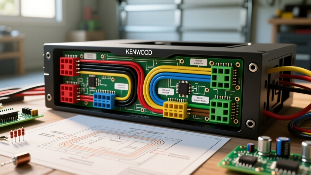

Strategic Planning for Your Kenwood Head Unit Installation
Upgrading to a modern receiver—such as the flagship Kenwood eXcelon DMX907S—is one of the most impactful modifications you can make to your vehicle's audio and infotainment ecosystem. However, the leap from unboxing the unit to enjoying pristine, noise-free audio hinges entirely on how you interpret and execute the wiring diagram for Kenwood harnesses. Rushing into the dashboard with a pair of cheap crimpers and electrical tape is a recipe for ground loops, memory loss, and blown internal traces.
This installation planning guide moves beyond the basic manual. We will decode the Consumer Technology Association (CTA) color standards, calculate amperage loads for high-power setups, and outline a professional bench-wiring workflow to ensure your 2026 car audio build is flawless on the first try.
Decoding the Standard Wiring Diagram for Kenwood
Kenwood adheres strictly to the Consumer Technology Association (CTA) mobile terminal power wire color codes. Before you make a single connection, map your vehicle's factory harness to the Kenwood pigtail using a multimeter, never relying solely on color-matching, as automakers frequently deviate from standard codes.
| Wire Color | Function | Planning Notes & Edge Cases |
|---|---|---|
| Yellow | Constant 12V (BATT / Memory) | Must have continuous power. Swapping this with the Red wire will cause your Kenwood unit to lose presets and DSP settings every time you turn off the ignition. |
| Red | Switched 12V (ACC / Ignition) | Triggers the unit on/off. If your vehicle uses a CAN-bus data network for accessory power (common in late-model VW and Chrysler), you will need a data module like the Axxess ASWC-1 to generate a 12V ACC signal. |
| Black | Chassis Ground | Must be terminated to bare, unpainted metal. Do not rely on the factory radio sleeve for grounding. |
| Blue/White | Amp Turn-On / Power Antenna | Critical Limit: Kenwood's internal transistor for this wire is typically capped at 300mA. Exceeding this will fry the head unit's internal circuitry. |
| Orange/White | Illumination / Dimmer | Connects to the vehicle's headlight circuit to dim the screen. Leave unconnected if your dash uses variable PWM dimming. |
| White / White-Black | Front Left Speaker (+/-) | Never ground the black-striped speaker wires to the chassis. Kenwood units use BTL (Bridge-Tied Load) amplifiers; grounding a negative speaker wire will instantly destroy the internal IC. |
| Gray / Gray-Black | Front Right Speaker (+/-) | Same BTL warning applies. Use a multimeter to verify no continuity to ground before powering on. |
| Green / Green-Black | Rear Left Speaker (+/-) | Ensure 18 AWG or thicker is used for runs longer than 6 feet to prevent high-frequency roll-off. |
| Purple / Purple-Black | Rear Right Speaker (+/-) | Verify phase alignment using a 9V battery pop-test or an audio polarity analyzer before final assembly. |
Amperage Loads and the 300mA Turn-On Trap
One of the most common failure modes in custom car audio occurs when installers misinterpret the Blue/White amp turn-on wire on the wiring diagram for Kenwood receivers. Modern installations often involve a multi-channel amplifier, a dedicated monoblock subwoofer amp, and an active DSP (Digital Signal Processor).
Expert Warning: If your remote turn-on wire needs to trigger more than two devices, the cumulative current draw will likely exceed the Kenwood head unit's 300mA internal limit. This will result in a blown surface-mount transistor on the Kenwood PCB, requiring a costly board-level repair.
The Relay Solution
For complex 2026 audio builds, always use a 12V automotive relay (such as the PAC TR-4 or a standard Bosch-style 30A relay). Wire the Kenwood's Blue/White wire to the relay's trigger terminal (Pin 85). Connect Pin 86 to ground, Pin 30 to a fused constant 12V source, and Pin 87 to the remote turn-on terminals of your amplifiers and DSP. This isolates the high-current draw from the Kenwood's delicate internal switching circuit.
Vehicle-Specific Harness Mapping
Cutting your vehicle's factory wiring is an outdated practice that destroys resale value and complicates future diagnostics. Instead, plan your install around a vehicle-specific T-harness or hardwire adapter. According to Crutchfield's installation guides, matching the Kenwood pigtail to an aftermarket adapter on your workbench is the gold standard for reliability.
- Honda/Acura (e.g., Metra 70-1761): These harnesses often include a Blue/Yellow wire for the factory amplifier turn-on. This must be connected to the Kenwood's Blue/White wire. Failure to do so will result in zero audio from the speakers, even if the head unit powers on perfectly.
- Ford/Lincoln (e.g., Axxess XSVI-2104-NAV): Late-model Fords use complex CAN-bus systems for chimes, navigation prompts, and accessory power. These harnesses feature a bulky black interface box. You must connect the Kenwood's Red (ACC) and Yellow (Constant) to the corresponding outputs on the Axxess box, not directly to the vehicle's raw 12V lines.
- GM/Bose Systems (e.g., Axxess GMOS-LAN-04): Factory Bose amplifiers require a specific 6V turn-on signal, not 12V. The interface module handles this step-down, but you must ensure the Kenwood's Blue/White wire is feeding the module's input.
Step-by-Step Bench Wiring Workflow
Do not attempt to crimp, solder, or heat-shrink wires while lying upside down in the vehicle's footwell. Plan for a two-phase installation: bench prep, followed by dash integration.
- Prep the Harnesses: Lay the Kenwood pigtail and your vehicle-specific adapter (e.g., Metra or Axxess) side-by-side on your workbench.
- Strip with Precision: Use a high-quality wire stripper like the Klein Tools 11063W (calibrated for 22-10 AWG). Strip exactly 1/4 inch of insulation. Exposing too much bare wire creates a short-circuit hazard; too little results in a weak mechanical crimp.
- Make the Connections: While soldering and heat-shrinking is traditional, modern adhesive-lined dual-wall heat shrink crimp connectors (like those from Knoweasy or Glarks) provide a superior, waterproof, and vibration-proof seal when done correctly. Use a hex-profile crimper, not a standard indent crimper, to ensure the copper strands are fully compressed.
- Seal the Connections: If using solder, slide 3M dual-wall heat shrink over the joint and apply heat until the inner adhesive melts and seals the ends. This prevents copper oxidation and 'green death' (copper chloride buildup) over the lifespan of the vehicle.
- Bench Test: Before touching the car, connect the harness to a 12V 5A bench power supply. Verify that the Kenwood unit powers on, the memory retains a preset station after power is cut, and the Blue/White wire outputs exactly 12V when the unit is on.
Edge Cases & Troubleshooting Failure Modes
Even with a perfect wiring diagram for Kenwood, real-world variables can introduce issues. Here is how to troubleshoot the most common edge cases:
Alternator Whine (Ground Loops)
If you hear a high-pitched whine that rises and falls with engine RPM, you have a ground loop. This occurs when the Kenwood head unit and the external amplifiers are grounded to different metal points with varying resistance. Fix: Ensure the Kenwood's black ground wire is terminated to the exact same chassis bolt or grounding block as your amplifier's main power ground. Sand the paint away to bare, shiny metal before tightening the ring terminal.
Unit Fails to Power On (Blown Fuse vs. Bad Ground)
Kenwood head units feature an inline 10A blade fuse on the yellow constant wire and often a secondary 10A fuse on the back of the chassis. If the unit is dead, check the inline fuse first. If the fuse is intact, use a multimeter to check for continuity between the black ground wire and the vehicle's chassis. A reading above 0.5 ohms indicates a poor ground connection that is starving the unit of current during the initial boot sequence.
DSP and 5V Preout Noise Floors
Flagship 2026 models like the Kenwood eXcelon series feature 5V RCA preouts designed to maximize the signal-to-noise ratio. If you are running long RCA cables alongside the vehicle's factory wiring harness, electromagnetic interference (EMI) from the alternator and CAN-bus lines will degrade the audio. Always route your RCA cables and speaker wires down the opposite side of the vehicle's center console from the main 12V power wire and the Kenwood's primary power harness.
Frequently Asked Questions
Can I use the Kenwood wiring diagram for a JVC head unit?
Yes. Since Kenwood and JVC merged under the JVCKENWOOD Corporation, their aftermarket head units share the exact same CTA-compliant wire color codes and pinouts. A wiring diagram for Kenwood will map 1:1 with a modern JVC receiver.
What gauge wire should I use to extend the Kenwood power harness?
The factory Kenwood pigtail is typically 18 AWG. If you need to extend the Yellow (Constant) or Red (ACC) wires to reach a distant fuse box, use 16 AWG or 14 AWG primary automotive wire. Never use a smaller gauge than the factory wire, as this creates a bottleneck that can cause voltage drop and erratic reboots under heavy bass transients.
Do I need to connect the Orange/White illumination wire?
Connecting the Orange/White wire allows the Kenwood screen to dim when you turn on your headlights, reducing glare at night. However, if your vehicle uses a digital CAN-bus dimming signal rather than a simple 12V analog wire, leave the Orange/White wire capped and insulated. You can manually adjust the screen brightness via the Kenwood's on-screen display settings.