
Decoding the Blueprint: Symbols and Safety Intent
A room electrical wiring diagram is more than just a map of where outlets and switches go; it is a legally binding blueprint that must adhere to the National Electrical Code (NEC). As municipalities continue to adopt and enforce the latest NEC standards through 2026, understanding the safety intent behind every line and symbol on your diagram is critical. Failing an electrical inspection not only delays construction but, more importantly, introduces severe fire and shock hazards. According to the National Fire Protection Association (NFPA), electrical failures or malfunctions account for tens of thousands of home structure fires annually. Reading your diagram through the lens of code compliance ensures your installation is both functional and safe.
NEC Receptacle Spacing: The 6-Foot Rule
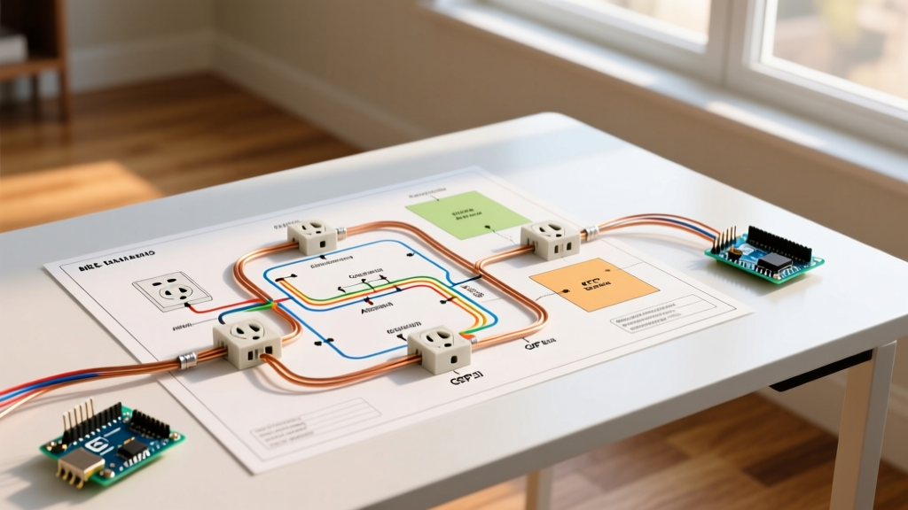
When reviewing the receptacle layout on your room electrical wiring diagram, the first compliance checkpoint is NEC Article 210.52. This section dictates the spacing of general-use receptacles in dwelling units.
The 6-Foot Rule: No point measured horizontally along the floor line of any wall space can be more than 6 feet from a receptacle outlet. Furthermore, any wall space 2 feet or more in width must have its own receptacle.
On your diagram, measure the distance between outlet symbols. If a wall is 14 feet long, a single outlet in the center leaves a 7-foot gap to the corners, violating the code. You must plot at least two outlets. Additionally, ensure your diagram accounts for doorways, fireplaces, and fixed cabinets, as these break the 'wall space' continuity and require the 6-foot measurement to restart from the edge of the obstruction.
Wire Gauge and Breaker Sizing Matrix
One of the most common errors in DIY room wiring is mismatching wire gauge to the circuit breaker. Your diagram must explicitly state the American Wire Gauge (AWG) and the corresponding overcurrent protection device (breaker) size. The Occupational Safety and Health Administration (OSHA) emphasizes that over-fusing a circuit is a primary cause of electrical fires, as the breaker will not trip before the wire insulation melts.
| Wire Gauge (Copper NM-B) | Breaker Size | Max Continuous Load (80%) | Typical Room Application |
|---|---|---|---|
| 14 AWG | 15 Amp | 1,440 Watts | Bedroom Lighting, Low-Draw Living Rooms |
| 12 AWG | 20 Amp | 1,920 Watts | Bathrooms, Kitchens, High-Load Living Areas |
| 10 AWG | 30 Amp | 2,880 Watts | Heavy Appliances (Not for standard room receptacles) |
Note: While 14 AWG is permissible for 15A lighting circuits in many jurisdictions, many professional electricians standardize on 12 AWG for all 20A room receptacle circuits to mitigate voltage drop over long runs and provide a safer thermal margin.
AFCI and GFCI Mandates: Protecting the Modern Room
Modern room electrical wiring diagrams must specify Arc-Fault Circuit Interrupter (AFCI) and Ground-Fault Circuit Interrupter (GFCI) protection. As of the latest code cycles, AFCI protection is required for nearly all 120-volt, single-phase, 15- and 20-amp branch circuits supplying outlets in dwelling unit rooms, including bedrooms, living rooms, family rooms, and closets.
Specifying the Right Hardware
Do not just write 'AFCI' on your diagram; specify the exact breaker type to ensure the panel schedule matches the physical installation. For a standard 15A bedroom circuit, you would specify a Combination-Type AFCI breaker, such as the Square D HOM115CAFI (approx. $38-$45) or the Eaton BR115AF. Combination AFCIs detect both parallel and series arcs, providing superior fire protection compared to older branch/feeder types.
For bathrooms or rooms with wet-bar sinks, your diagram must indicate GFCI protection. This can be achieved via a GFCI breaker (e.g., Square D HOM120GFI, approx. $45) or by daisy-chaining from a GFCI receptacle (e.g., Leviton GFNT1-W, approx. $18) placed at the first point of the circuit.
Edge Case: Multi-Wire Branch Circuits (MWBC)
If your diagram utilizes a shared neutral (MWBC) to feed two separate room circuits from a single 3-wire cable, strict NEC rules apply. NEC 210.4 requires a simultaneous disconnect mechanism. You must specify a 2-pole breaker or approved handle ties. Furthermore, because AFCI protection is required, you must use a 2-pole AFCI breaker (e.g., Square D HOM220CAFI, approx. $75-$90) to monitor the shared neutral correctly without nuisance tripping.
Mastering Box Fill Calculations (NEC Article 314)
A beautifully drawn room electrical wiring diagram will still fail inspection if the physical junction boxes are overcrowded. NEC Article 314.16 dictates box fill calculations to prevent wire insulation damage and heat buildup. When planning your diagram, you must calculate the cubic inch capacity required for every box.
Step-by-Step Calculation for a Standard Outlet Box:
- Conductors: Each hot and neutral wire entering and leaving the box counts as 1 volume allowance. (e.g., 1 incoming 12/2 and 1 outgoing 12/2 = 4 conductors).
- Clamps: All internal cable clamps count as 1 volume allowance based on the largest wire.
- Devices: Each switch or receptacle counts as 2 volume allowances.
- Grounds: All equipment grounding conductors combined count as 1 volume allowance.
Practical Example (12 AWG Wire):
According to NEC Table 314.16(B), each 12 AWG conductor requires 2.25 cubic inches.
Let's calculate a box with one incoming 12/2, one outgoing 12/2, one receptacle, and internal clamps:
4 conductors (hots/neutrals) x 2.25 = 9.0 cu in.
1 device (receptacle) x 2 x 2.25 = 4.5 cu in.
1 ground x 2.25 = 2.25 cu in.
1 clamp x 2.25 = 2.25 cu in.
Total Required Volume = 18.0 cubic inches.
If your diagram routes three cables through a single junction box, the required volume will easily exceed a standard 20-cu-in 'old work' box. Always specify oversized boxes (e.g., 24-cu-in or 30-cu-in deep boxes) on your diagram when multiple runs converge.
Common Failure Modes and Inspection Red Flags
Based on data from the U.S. Consumer Product Safety Commission (CPSC), improper wiring remains a leading cause of residential electrocution and property damage. Inspectors actively look for these specific diagram-to-reality discrepancies:
- Staple Placement: Diagrams should note that NM-B cable must be stapled within 8 inches of the box and every 4.5 feet thereafter. Missing staples lead to sagging wires and drywall screw punctures.
- Neutral Pigtailing: Never use the receptacle's internal brass/silver tabs as a splice for the neutral wire on a multi-circuit run. The diagram must show wire-nut pigtails to ensure the downstream circuit doesn't lose its neutral if the upstream device is removed.
- Box Depth: Using shallow 1.5-inch deep boxes for smart switches or dimmers. Modern smart switches (like the Lutron Caseta PD-6WCL) have deep bodies and require a minimum 2.5-inch deep box to accommodate the wiring and heat dissipation.
Frequently Asked Questions
Can I mix 14 AWG and 12 AWG wire on the same 20A room circuit?
No. While physically possible, NEC 240.4(D) strictly limits 14 AWG copper to a maximum 15A overcurrent device. If your room electrical wiring diagram specifies a 20A breaker, every inch of the circuit conductors must be 12 AWG or larger. Mixing gauges creates a bottleneck where the 14 AWG wire can overheat and catch fire before the 20A breaker trips.
Do lighting circuits in a bedroom require AFCI protection?
Yes. Under current NEC guidelines, the AFCI mandate applies to all 15A and 20A branch circuits supplying outlets and devices in bedrooms. This includes hardwired lighting fixtures, ceiling fans, and smoke detectors (unless specifically exempted by local amendments for battery-backed/smoke-only circuits). Plan for AFCI breakers on your lighting panel schedule.
How do I handle a room with a fireplace on the wiring diagram?
A fireplace breaks the continuous wall space. You cannot route a receptacle cable directly behind or above a masonry fireplace firebox due to heat degradation of the NM-B insulation. Your diagram must route wiring around the perimeter, maintaining at least a 2-inch clearance from the outside of the masonry chimney flue, or use mineral-insulated (MI) cable or rigid metal conduit if routing near high-heat zones is unavoidable.