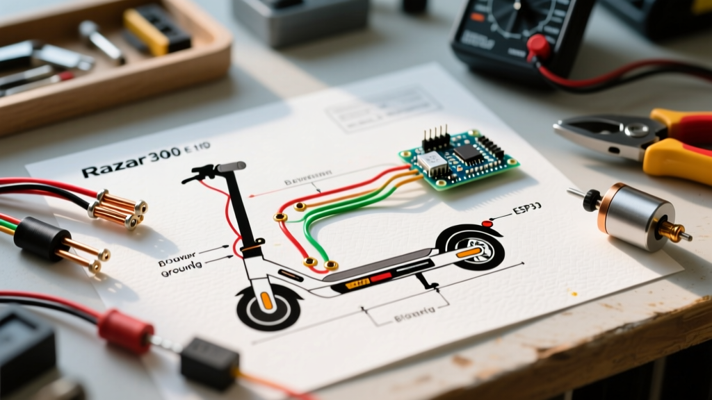

Decoding the Wiring Diagram for Razor Scooter Models
When your Razor E300, E100, or Pocket Mod suddenly refuses to move, the difference between a $15 fix and a $150 replacement often comes down to how well you can read a wiring diagram for Razor scooter systems. In 2026, with supply chain shifts making OEM replacement parts slightly more expensive (a genuine Razor 24V speed controller now averages $32 to $45), diagnosing the exact fault node is critical. Instead of blindly swapping parts, professional repair technicians use the schematic to isolate the failure point in minutes.
This guide will walk you through the core architecture of Razor's 24V brushed motor systems, decode the proprietary wire color matrix, and provide step-by-step troubleshooting flows using a digital multimeter.
The 5-Node Architecture of a 24V Razor System
Before tracing a fault, you must understand the five primary nodes present in almost every wiring diagram for Razor scooter models (specifically the E100, E200, E300, and Pocket Mod). The system operates on a simple DC loop:
- Node 1: The Power Source (Battery Pack): Typically two 12V 7Ah or 10Ah Sealed Lead Acid (SLA) batteries wired in series to create 24V nominal.
- Node 2: The Circuit Breaker: A thermal or magnetic resettable breaker (usually 20A for E100, 30A for E300) located inline on the positive battery lead to prevent wire meltdowns during motor stalls.
- Node 3: The Speed Controller: The 'brain' of the scooter. It takes low-current signals from the throttle and switches high-current power from the battery to the motor via internal MOSFETs.
- Node 4: The Throttle Assembly: A Hall-effect sensor or potentiometer that sends a variable voltage signal (usually 0.8V to 3.6V) to the controller.
- Node 5: The Motor & Brake Switch: A 24V brushed DC motor paired with a normally-closed (NC) brake switch that cuts the throttle signal when the brake lever is pulled.
Razor Wire Color Matrix & Pinouts
Razor does not always adhere to standard automotive wiring colors, which is why relying on the specific wiring diagram for Razor scooter variants is essential. Below is the standard color code matrix for the ubiquitous 3-wire throttle and 24V power loops found in most post-2020 models.
| Wire Color | Function / Node | Voltage / Specification | Common Failure Mode |
|---|---|---|---|
| Red (Thick) | Battery Positive (+) | 24V Nominal (27.6V Peak) | Corrosion at spade terminal |
| Black (Thick) | Battery Negative / Ground (-) | 0V Reference | Loose Molex connector pin |
| Red (Thin) | Throttle 5V Supply | 4.8V - 5.2V DC | Internal controller regulator failure |
| Black (Thin) | Throttle Ground | 0V Reference | Wire fray at handlebar pivot |
| Blue or Green | Throttle Signal Return | 0.8V (Rest) to 3.6V (Full) | Hall sensor burnout |
| White / Yellow | Brake Switch Loop | 5V pulled to Ground when braking | Switch misalignment / stuck closed |
Step-by-Step Troubleshooting Using the Diagram
When a scooter arrives on your bench, do not immediately open the deck. Use the wiring diagram to perform logical deduction. Here are the three most common scenarios and how to trace them.
Scenario A: Scooter is Completely Dead (No Lights, No Motor)
If the scooter shows zero signs of life, the fault lies between Node 1 and Node 2.
- Check the XLR Charge Port: Set your multimeter to DC Voltage. Probe the two outer pins of the XLR charging port. According to Battery University, a fully charged 24V SLA system should read between 25.8V and 27.6V. If you read 0V, the inline fuse or circuit breaker has tripped.
- Trace the Breaker: Open the deck. Locate the inline circuit breaker on the thick red wire. Test for continuity across the breaker. If it reads 'OL' (Open Loop), the breaker has failed or tripped due to a downstream short.
- Inspect the Power Switch: The power switch simply bridges the battery positive to the controller's 'Lock' or 'Ignition' wire. If the switch has melted internals (common in older E300 models), the controller never receives the wake-up signal.
Scenario B: Motor Stutters or Cuts Out Under Load
This is the hallmark of a voltage drop or a failing throttle signal. The wiring diagram shows that the controller monitors the battery voltage and will engage a Low Voltage Cutoff (LVC) if it drops below 21V.
- The Load Test: Elevate the rear wheel. Run the motor at full throttle. If it spins fine in the air but dies when you sit on it, your battery pack has high internal resistance (sulfation) and is sagging below the 21V LVC threshold under load. Replace the SLA batteries.
- The Throttle Signal Test: Back-probe the thin blue/green signal wire at the controller connector. As per Fluke's multimeter testing guidelines, monitor the DC voltage while twisting the throttle. It should sweep smoothly from ~0.8V to ~3.6V. If the voltage jumps erratically or drops to 0V mid-twist, the Hall-effect sensor inside the throttle is destroyed. A replacement OEM throttle costs roughly $14 to $18.
Scenario C: Motor Will Not Engage, But Power is On
If the power light is on but the motor won't spin, the controller's safety interlocks are preventing engagement. The wiring diagram highlights two main interlocks: the brake switch and the kick-start sensor.
Expert Tip: Razor scooters require a 'kick-to-start' mechanism to prevent accidental throttle twists from causing runaway scooters. The controller looks for a back-EMF voltage spike from the motor (indicating it is already spinning at ~3 MPH) before it will engage the MOSFETs. If your kick-start sensor (a small magnetic reed switch near the rear axle on some models) is misaligned, the controller will never enable the drive circuit.
Additionally, check the brake switch. It is a Normally-Closed (NC) circuit. If the brake lever is slightly bent, or the switch is stuck, it continuously sends a 'braking' signal to the controller, cutting the motor output. Unplug the brake switch Molex connector at the controller; if the scooter suddenly works, replace the $6 brake switch.
Edge Case: 2026 Lithium (LiFePO4) Upgrades
Many enthusiasts are upgrading their aging Razor E300s from heavy SLA batteries to 24V Lithium Iron Phosphate (LiFePO4) packs. When doing this, the wiring diagram requires a critical modification.
SLA batteries can safely be drained down to roughly 21V. However, a 7S or 8S Lithium pack will be destroyed if drained below its BMS (Battery Management System) cutoff, and the Razor controller's hardcoded 21V LVC will not protect a lithium pack correctly. When integrating a lithium pack, you must wire the BMS's discharge negative wire directly to the controller's main ground, bypassing the scooter's native low-voltage protection logic and relying entirely on the BMS to prevent over-discharge. Always consult your specific BMS wiring diagram alongside the Razor schematic to ensure the charge and discharge ports are isolated correctly.
Safety and Connector Best Practices
When repairing wires based on the schematic, avoid using cheap twist-on wire nuts inside the scooter deck. The high-vibration environment of a scooter will shake them loose, causing arcing and melted decks. Instead, use the following standards:
- Soldering & Heat Shrink: For permanent inline repairs, solder the connection and seal it with adhesive-lined marine-grade heat shrink tubing.
- Molex Connectors: If a pin is burnt inside a Molex housing, do not just tape it. Use a proper crimping tool (like the SN-28B) to crimp new 2.54mm or 3.96mm pitch pins, matching the OEM specifications found on Razor Official Support documentation.
- Dielectric Grease: Apply a small dab of dielectric grease to the XLR charge port and battery spade terminals to prevent moisture ingress, which is the number one cause of ghost-draining and corrosion in outdoor-stored scooters.
Final Thoughts
Mastering the wiring diagram for Razor scooter models transforms a frustrating dead toy into a simple, logical puzzle. By understanding the 5-node architecture, respecting the color codes, and using a multimeter to verify voltage thresholds at the controller, you can accurately diagnose 95% of all electrical faults without wasting money on unnecessary replacement parts. Keep your schematic handy, trust your meter, and always disconnect the main battery loop before probing internal controller pins.