
Decoding the Wiring Diagram for Outside AC Unit Condensers
Understanding the electrical schematic inside your condenser unit is critical for safe troubleshooting, component replacement, and system optimization. While every manufacturer provides a specific schematic taped to the inside of the access panel, the fundamental architecture of a split-system air conditioner remains remarkably consistent. This guide breaks down the standard wiring diagram for outside AC unit configurations, translating complex schematics into actionable, real-world electrical pathways.
CRITICAL SAFETY WARNING: Before opening the electrical control box, always shut off the high-voltage disconnect switch located near the unit and trip the corresponding double-pole breaker in your main panel. Verify zero voltage at the contactor line terminals using a True-RMS multimeter (such as the Fluke 117) before touching any wires. According to the National Fire Protection Association (NFPA), failure to follow Lockout/Tagout (LOTO) procedures is a leading cause of severe arc flash injuries in residential HVAC servicing.
The Two Distinct Electrical Circuits
When analyzing a condenser wiring diagram, you must mentally separate the system into two completely isolated circuits. Mixing these up is the most common cause of catastrophic control board failure.
1. The High-Voltage Power Circuit (208/230V AC)
This circuit supplies the raw power required to run the compressor and the condenser fan motor. It originates from your home's main electrical panel via a double-pole breaker, travels through the exterior shut-off box, and enters the unit's control box. It operates strictly on 208V to 230V, single-phase power and utilizes heavy-gauge copper wiring (typically 10 AWG or 8 AWG THHN/THWN-2).
2. The Low-Voltage Control Circuit (24V AC)
This circuit acts as the 'brain' trigger. It originates from the 24V transformer inside your indoor air handler or furnace. The thermostat calls for cooling, sending a 24V signal down the 'Y' (compressor) and 'C' (common) wires to the outside unit. This low-voltage signal energizes the magnetic coil on the contactor, pulling the high-voltage contacts closed to start the system.
Core Component Terminal Mapping Matrix
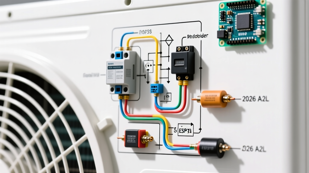
The heart of the outside unit's electrical system revolves around three primary components: the contactor, the dual run capacitor, and the motors. Below is the standard terminal mapping you will find on 95% of residential wiring diagrams.
| Component | Terminal Label | Function & Wiring Destination |
|---|---|---|
| Contactor | L1 & L2 (Line) | Receives 208/230V incoming power from the exterior disconnect box. |
| T1 & T2 (Load) | Sends 208/230V power to the compressor and fan motor when the coil is energized. | |
| A1 & A2 (Coil) | Receives the 24V AC signal from the indoor unit's 'Y' and 'C' thermostat wires. | |
| Dual Run Capacitor | C (Common) | Receives the shared 208/230V leg (usually from T1 on the contactor). |
| HERM (Hermetic) | Connects directly to the start winding of the sealed compressor. | |
| FAN | Connects directly to the start winding of the condenser fan motor. | |
| Compressor | R (Run), S (Start), C (Common) | C connects to T2 (contactor); R connects to T1 (contactor); S connects to HERM (capacitor). |
2026 HVAC Updates: A2L Refrigerant Sensor Wiring
If you are looking at a wiring diagram for outside AC unit models manufactured for the 2025/2026 production cycles, you will notice a significant addition to the standard schematic: A2L Refrigerant Leak Detection Sensors.
Due to the EPA-mandated transition away from R-410A toward lower Global Warming Potential (GWP) refrigerants like R-32 and R-454B, modern condensers now feature integrated safety circuitry. According to the U.S. Environmental Protection Agency (EPA), these mildly flammable A2L refrigerants require active mitigation. On 2026 schematics, you will see a low-voltage sensor wired in series with the 24V contactor coil or integrated into an outdoor control board. If the sensor detects refrigerant pooling near the compressor, it physically breaks the 24V control circuit, preventing the contactor from engaging and eliminating ignition risks. When troubleshooting a 'no-start' condition on a 2026 unit, always verify the continuity of the A2L safety loop before replacing the contactor.
NEC Wire Gauge and Overcurrent Protection Sizing
Proper wire sizing is non-negotiable and is strictly governed by Article 440 of the National Electrical Code (NEC). The manufacturer's data plate will list two critical values: Minimum Circuit Ampacity (MCA) and Maximum Overcurrent Protection (MOP).
- MCA dictates the minimum wire gauge and ensures the wire will not overheat under continuous load.
- MOP dictates the maximum breaker size allowed to prevent nuisance tripping during the compressor's high-inrush Locked Rotor Amp (LRA) startup phase.
| Breaker Size (MOP) | Minimum Copper Wire Gauge (THHN/THWN-2) | Typical Unit Tonnage |
|---|---|---|
| 20 Amp | 12 AWG | 1.5 to 2 Tons |
| 30 Amp | 10 AWG | 2.5 to 3 Tons |
| 40 Amp | 8 AWG | 3.5 to 4 Tons |
| 50 Amp | 6 AWG | 5 Tons |
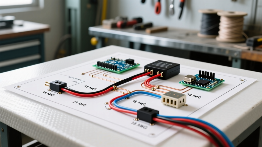
Note: For control wiring, 18 AWG solid copper thermostat wire is standard. However, if the wire run from the indoor air handler to the outside condenser exceeds 75 feet, upgrade to 16 AWG to prevent voltage drop below the 20V threshold required to reliably pull in the contactor coil.
Real-World Failure Modes and Troubleshooting
When a system fails, the wiring diagram acts as your diagnostic map. Here are the most common electrical failure modes encountered in the field:
1. Pitted Contactor Contacts
Over years of operation, the high-inrush current of the compressor causes microscopic arcing across the contactor's T1/T2 and L1/L2 terminals. This pitting increases electrical resistance, leading to a voltage drop. If the compressor receives less than 195V during operation, it will overheat and trip its internal thermal overload. Fix: Inspect the contactor face. If it looks burnt or pitted, replace it with an exact-match unit (e.g., a Packard C330B for a 30A, 24V coil application, typically costing $20 to $35).
2. Weak or Failed Dual Run Capacitor
Capacitors degrade over time due to thermal stress. A 45/5µF capacitor might drop to 38µF, causing the compressor to draw excessive amperage on the run winding. Diagnostic: Use a multimeter with a capacitance setting. If the reading is more than 6% below the rated microfarads printed on the label, replace it. Premium models like the AmRad Titan Pro series ($25-$40) feature reinforced dielectrics that better withstand extreme ambient heat.
3. Swapped HERM and FAN Terminals
A common DIY mistake after replacing a capacitor is wiring the compressor start wire to the FAN terminal and the fan start wire to the HERM terminal. Because the microfarad ratings are vastly different (e.g., 45µF for the compressor vs. 5µF for the fan), the fan motor will attempt to start with massive torque, potentially damaging its windings, while the compressor will fail to start and hum loudly. Always trace the wires back to their respective motor housings using the schematic on the access panel.
Maintaining Electrical Integrity
Beyond the components themselves, the physical routing of the wires matters. High-voltage and low-voltage wires should never be bundled tightly together or run through the same conduit knockout, as the 230V electromagnetic field can induce 'ghost voltages' in the 24V control lines, leading to erratic thermostat behavior. Always route the 18 AWG control wire through a separate, dedicated knockout on the condenser housing.
For comprehensive maintenance schedules and efficiency standards regarding split-system air conditioners, refer to the U.S. Department of Energy's Energy Saver guidelines. Proper electrical maintenance, combined with regular coil cleaning, ensures your system operates safely and at peak SEER2 efficiency ratings throughout its lifespan.