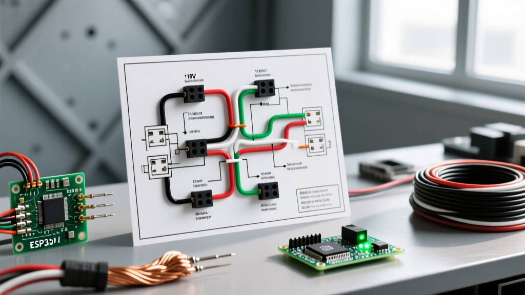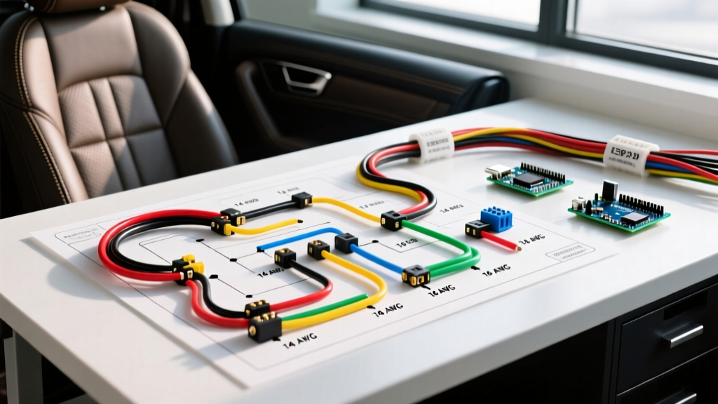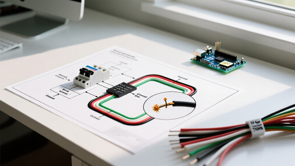

Before a single staple is driven or a wire is stripped, the success of any residential electrical project is determined by the blueprint. A household electrical wiring diagram is not merely a map of where outlets go; it is a critical planning tool that dictates panel capacity, wire gauge selection, and compliance with the National Electrical Code (NEC). As we navigate the 2026 NEC adoption cycle, which features expanded Arc-Fault (AFCI) and Ground-Fault (GFCI) requirements, interpreting your diagram correctly during the pre-installation phase is non-negotiable for safety and efficiency.
Decoding Symbology for Pre-Install Planning
Standard residential blueprints utilize ANSI/NEMA standard symbols. However, an expert installer looks beyond the basic symbols to identify hidden material requirements. For instance, a standard duplex receptacle symbol might imply a simple 12/2 NM-B run, but if that symbol is bisected by a diagonal line (indicating a split-wired, switch-controlled outlet), your planning must immediately shift to include 12/3 NM-B cable or a smart switch with a neutral pigtail.
| Diagram Symbol / Notation | Standard Meaning | Planning & Material Implication |
|---|---|---|
| Circle with 'S' inside | Single-pole switch | Requires 14/2 or 12/2 to the switch box; verify neutral requirement for smart switches. |
| Receptacle bisected by line | Split-wired (half-hot) outlet | Mandates 12/3 NM-B (with red traveler) or a dual-pole AFCI breaker if on a MWBC. |
| Box with 'GFCI' or 'GF' | Ground-Fault protected | Plan for 20A GFCI receptacle (e.g., Leviton GFNT2) or a GFCI breaker; check box depth (requires 22.5 cu in box). |
| Dotted line connecting devices | Switch leg / Traveler | Identifies 3-way or 4-way switch loops; requires 12/3 or 12/4 cabling. |
Panel Capacity and Load Calculation Mapping
Your wiring diagram must be cross-referenced with a formal load calculation per NEC Article 220. A common mistake during the planning phase is counting the number of physical breakers rather than calculating the Volt-Ampere (VA) load. According to the National Fire Protection Association (NFPA), general lighting and receptacle loads are calculated at 3 VA per square foot, but specific appliance circuits require dedicated allocations.
Expert Planning Rule: Never plan a panel based on physical spaces alone. A 200-Amp residential service provides roughly 48,000 VA at 240V. If your diagram shows two 20A Small Appliance Branch Circuits (SABC), one 20A Laundry circuit, and a 50A Range circuit, you must allocate 1,500 VA for each SABC and Laundry circuit, and apply demand factors to the range before tallying the total panel schedule.
Step-by-Step Load Mapping from Diagram to Panel
- Identify Dedicated Circuits: Highlight every major appliance on the diagram (HVAC, Water Heater, Range, Dryer). Assign their exact nameplate amperage to specific 240V double-pole breaker slots.
- Map SABC and Laundry: Ensure the kitchen and dining areas on the diagram have at least two 20A circuits (NEC 210.11(C)(1)). These cannot serve lighting or other rooms.
- Apply Continuous Load Derating: If the diagram indicates hardwired lighting or HVAC equipment expected to run for 3 hours or more, apply the 80% rule (NEC 210.20). A 20A breaker can only be planned for 16A of continuous load.
- Balance the Phases: As you assign 120V circuits from the diagram to the panel schedule, alternate them between Phase A and Phase B to ensure the neutral bus bar does not carry excessive unbalanced current.
Strategic Routing: Voltage Drop and Wire Sizing
A household electrical wiring diagram shows the logical connections, but it rarely accounts for physical distance. Voltage drop is the silent killer of appliance longevity and lighting performance. The NEC recommends a maximum 3% voltage drop for branch circuits. When planning your wire pulls, you must measure the actual routing distance from the panel to the furthest outlet on the diagram.
Wire Gauge Selection Matrix for Long Runs (120V Circuits)
If your diagram shows an outdoor receptacle or a detached garage subpanel feed, use this matrix to adjust your Bill of Materials (BOM) from standard 12 AWG to larger gauges to mitigate voltage drop.
| Circuit Amperage | Standard Wire (NEC Min) | Max Length for <3% Drop | Upsized Wire (80-120 ft) | Upsized Wire (120-160 ft) |
|---|---|---|---|---|
| 15 Amp | 14 AWG Copper | ~50 feet | 12 AWG Copper | 10 AWG Copper |
| 20 Amp | 12 AWG Copper | ~45 feet | 10 AWG Copper | 8 AWG Copper |
Note: Upsizing wire requires verifying that the termination lugs on your breakers and receptacles are rated for the larger gauge. Most standard 20A receptacles (like the Leviton 5352) will not accept 8 AWG solid wire; you must plan for pigtailing with a wire nut or using a deep junction box.
Multi-Wire Branch Circuits (MWBC) and Shared Neutrals
To save on copper and panel space, older diagrams frequently utilize Multi-Wire Branch Circuits (MWBC), where two 120V hot wires (typically black and red) share a single white neutral. If your planning involves an existing diagram or a new high-density layout, strict adherence to NEC 210.4 is required.
- Simultaneous Disconnect: You must plan for a 2-pole breaker (e.g., Square D QO220) or an approved handle tie (e.g., Square D QO2HW) to ensure both hot legs are disconnected simultaneously during maintenance.
- AFCI Complications: As of the 2026 NEC cycle, AFCI protection is required in almost all residential living spaces. Standard single-pole AFCI breakers will trip immediately on an MWBC due to neutral current imbalance. Planning Fix: You must specify 2-pole AFCI breakers (e.g., Eaton BR220AFCI) for any MWBC on your diagram, which are significantly more expensive and take up two full panel slots.
- Neutral Pigtailing: Plan to instruct installers to pigtail the neutral in every receptacle box on the MWBC. Breaking the neutral daisy-chain while the circuit is live will send 240V through connected 120V appliances, instantly destroying them.
Generating the Material Takeoff (BOM) from Your Diagram
The final step in the planning phase is translating the household electrical wiring diagram into a precise Bill of Materials. Vague estimates lead to mid-project delays. Use the diagram to count exact nodes and apply the following multipliers:
- Wire Length: Measure the diagram's linear footage, add 15% for vertical drops, stud weaving, and panel slack. Add 12 inches per receptacle box and 18 inches per panel termination.
- Box Volume (NEC 314.16): Count the number of wires entering each box on the diagram. A standard single-gang box (18 cu in) is only sufficient for roughly four 12 AWG wires. If the diagram shows a device with a line, load, neutral, and ground passing through, you must upgrade to a 22.5 cu in deep box.
- Breaker Specifics: Match the panel manufacturer exactly. A Siemens panel requires Siemens QT or QAF2 breakers; using classified but non-native breakers (like Eaton CL) is only permissible if explicitly listed on the panel's wiring diagram label. Always verify the panel schedule before ordering.
Frequently Asked Questions
Can I modify the household electrical wiring diagram after the rough-in inspection?
Minor modifications, such as moving a receptacle a few feet along the same stud bay, generally do not require a diagram revision. However, adding new circuits, upgrading amperage, or altering the panel schedule requires submitting an updated diagram to your local Authority Having Jurisdiction (AHJ). The Electrical Safety Foundation International (ESFI) strongly advises against undocumented changes, as they create severe hazards for future electricians troubleshooting the system.
How do I plan for smart home integrations on a standard wiring diagram?
Standard diagrams rarely account for smart switches, which require a neutral wire to power their internal radios (Zigbee, Z-Wave, or Wi-Fi). When planning, mandate 12/3 NM-B or 14/3 NM-B to all switch boxes, even if the diagram only calls for a simple single-pole switch leg. This 'future-proofs' the installation for smart relays like the Lutron Caseta or Shelly relays without requiring a costly rewire later.
What is the planning protocol for EV charger circuits?
If your diagram includes an Electric Vehicle Supply Equipment (EVSE) outlet, treat it as a continuous load. A 50A NEMA 14-50 receptacle must be installed on a 60A breaker (or hardwired at 40A on a 50A breaker) to satisfy the 125% continuous load rule. Plan for 6 AWG copper THHN in conduit or 4 AWG aluminum SER cable, and ensure the panel has the physical space and VA capacity to support a 12,000W continuous draw.