
Understanding the Chevy 350 Starter Circuit Architecture
The Small Block Chevy (SBC) 350 cubic-inch V8 is arguably the most popular and widely swapped engine in automotive history. Whether you are restoring a 1969 Camaro, wiring a 1985 C10 truck, or dropping a modern crate motor into a custom hot rod in 2026, understanding the wiring diagram for Chevy 350 starter systems is non-negotiable. The vast majority of these engines utilize the legendary Delco-Remy 10MT direct-drive starter or a modern high-torque planetary mini-starter.
Unlike modern vehicles controlled by complex CAN-bus networks and body control modules (BCMs), the classic Chevy 350 starter circuit is a beautifully simple, high-amperage analog system. However, its simplicity often leads to incorrect wiring, resulting in slow cranking, melted harnesses, or the dreaded "heat soak" no-start condition. This guide provides a comprehensive, expert-level breakdown of the wiring topology, terminal identification, and modern upgrade paths.
Anatomy of the GM Delco-Remy Starter Solenoid
To wire the system correctly, you must first understand the solenoid mounted on top of the starter motor. The solenoid acts as both a heavy-duty relay (connecting the battery to the starter motor) and a mechanical lever (engaging the pinion gear with the flexplate). For official wiring schematics and torque specifications, restorers should always consult Helm Incorporated (Official GM Service Manuals).
Terminal Identification
- BAT (Battery) Terminal: The large 3/8-inch or 5/16-inch threaded stud. This receives constant 12V power directly from the battery positive terminal. It is always "hot."
- S (Start) Terminal: The small 1/4-inch spade or threaded stud (usually closest to the engine block). This receives the 12V trigger signal from the ignition switch when the key is turned to the "Crank" position.
- I (Ignition) / R (Resistor) Terminal: The second small 1/4-inch spade or stud (usually closest to the fender). This terminal outputs 12V only while the starter is actively cranking. It is used to bypass the ballast resistor wire in points-style ignition systems, or to provide a dedicated 12V feed to an HEI distributor during cranking.
Step-by-Step Wiring Diagram for Chevy 350 Starter
Follow this exact sequence to ensure proper voltage delivery and safety. According to SAE International Wiring Standards, high-amperage circuits require specific overcurrent protection and routing protocols.
Step 1: Main Battery Power (BAT Terminal)
Run a heavy-gauge cable from the battery positive terminal to the starter BAT terminal. In 2026, best practice dictates installing a 175A to 250A Marine-rated ANL or Mega Fuse within 12 inches of the battery positive post. This protects the main cable from shorting to the chassis and causing an electrical fire.
Step 2: Ignition Trigger Circuit (S Terminal)
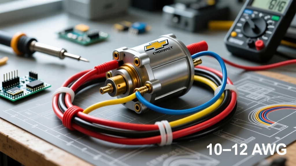
The 'S' terminal requires a 10 AWG or 12 AWG wire. This wire routes from the ignition switch's "Start" terminal, through the vehicle's Neutral Safety Switch (or clutch pedal interlock switch), and down to the starter 'S' terminal.
Routing Tip: Keep this trigger wire away from exhaust manifolds. Use high-temperature cross-linked polyethylene (XLPE) insulated wire rather than standard PVC, which becomes brittle and cracks near SBC exhaust headers.
Step 3: Ignition Coil Bypass (I Terminal)
If you are running a traditional points-style distributor with a resistance wire (or external ballast resistor), you must wire the 'I' terminal to the positive side of the ignition coil. During cranking, battery voltage drops to 9V-10V; the 'I' terminal provides a direct 12V bypass to ensure a strong spark while starting. If you have upgraded to a modern EFI system or a standard GM HEI distributor, this terminal is generally left disconnected, as the HEI has its own internal coil and requires a switched 12V source from the ignition switch's "Run" circuit.
Wire Gauge Selection Matrix for 350 V8 Starters
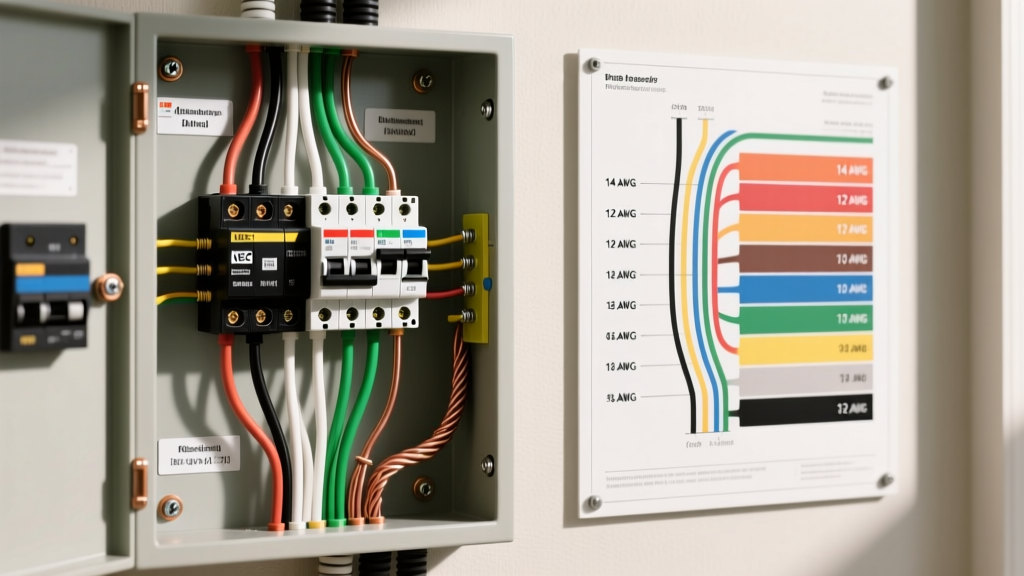
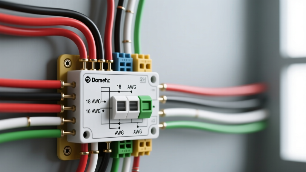
Undersized wiring is the number one cause of slow-cranking Chevy 350s. Voltage drop across a thin wire robs the starter of the amperage it needs to generate torque. Use the matrix below to select the correct SAE-compliant wire gauge based on your specific starter type and cable length.
| Starter Type | Avg. Amp Draw (Under Load) | Recommended Main Cable (Under 8ft) | Recommended Main Cable (Over 8ft) | Trigger Wire Gauge |
|---|---|---|---|---|
| Standard Delco 10MT (Reman) | 120A - 150A | 4 AWG | 2 AWG | 12 AWG |
| High-Torque Mini (e.g., Powermaster) | 160A - 200A | 2 AWG | 1/0 AWG | 10 AWG |
| Heavy Duty Gear Reduction (Diesel Swap) | 220A+ | 1/0 AWG | 2/0 AWG | 10 AWG |
High-Torque Mini Starter vs. Standard Delco 10MT
When wiring a new build in 2026, you must decide between the original equipment style and modern gear-reduction alternatives.
- Standard Delco 10MT: Inexpensive ($60–$90), historically accurate for restorations, but heavy, draws high amperage, and highly susceptible to heat soak. Requires strict adherence to factory heat shields.
- High-Torque Mini Starter (e.g., Powermaster 9100 or TCI 9200): Priced between $160 and $230. These utilize a planetary gear-reduction design (similar to modern LS starters). They are half the weight, provide 40% more cranking torque, and feature offset billet aluminum housings that physically move the solenoid away from the exhaust headers, drastically reducing heat soak.
Curing Heat Soak: The Remote Solenoid Trick
Heat soak occurs when exhaust header radiation bakes the starter solenoid. As the copper windings inside the solenoid heat up, electrical resistance increases. A hot solenoid may require 14+ volts to engage, but your battery is only supplying 11.5 volts during a crank attempt. The result: a single loud "click" and no engine rotation.
While ceramic header coatings and titanium heat shields help, the ultimate hot-rodder's fix is installing a remote Ford-style starter solenoid (relay) on the fender well.
Remote Solenoid Wiring Steps:
- Mount a standard Ford starter relay (approx. $15) on the inner fender, away from engine heat.
- Run your main 2 AWG battery cable to the relay's large "Battery" post.
- Run a second 2 AWG cable from the relay's "Starter" post down to the Chevy starter's BAT terminal.
- The Bypass Jump: Install a short jumper wire on the Chevy starter connecting the large BAT terminal directly to the small 'S' terminal. This ensures the Chevy solenoid engages the moment power reaches it.
- Route your ignition switch trigger wire to the small 'S' spade on the remote Ford relay.
Result: The ignition switch only has to carry the tiny amperage required to trigger the remote relay on the cool fender. The heavy amperage travels a much shorter distance directly from the battery to the starter, eliminating voltage drop and heat-soak failures entirely.
Troubleshooting Common Chevy 350 Starter Wiring Failures
Before replacing a starter that seems dead, perform these diagnostic checks:
- The Voltage Drop Test: Set your multimeter to DC Volts. Place the red probe on the battery positive post and the black probe on the starter BAT terminal. Have an assistant crank the engine. If the meter reads more than 0.5V, your main cable or battery terminals are corroded and restricting current flow.
- Neutral Safety Switch Faults: If the starter works when you jump the battery terminal to the 'S' terminal with a screwdriver, but not via the ignition key, the issue is upstream. Check the neutral safety switch for continuity and ensure the ignition switch is actually outputting 12V on the start wire.
- Engine Ground Strap Deficiency: The starter motor grounds through its aluminum housing to the cast-iron engine block. If your engine ground strap (connecting the block to the chassis/battery negative) is missing or corroded, the starter will attempt to ground through the throttle cable or transmission shift linkage, melting them instantly. Always use a minimum 2 AWG ground strap from the cylinder head to the chassis.
Frequently Asked Questions
Do I need a shim for my Chevy 350 starter?
It depends on the flexplate and starter nose cone combination. GM produced 153-tooth and 168-tooth flexplates. If your starter pinion gear binds or whines after engagement, you may need to install 1/16-inch steel shims between the starter mounting block and the engine to achieve the correct gear mesh clearance (typically 0.020" to 0.035").
Can I use a 1-wire alternator with this starter diagram?
Yes. A 1-wire alternator (like the popular Powermaster 17294) connects its single large output wire directly to the starter's BAT terminal alongside the main battery cable. This creates a centralized, high-amperage distribution point at the starter, simplifying the engine bay wiring harness significantly.