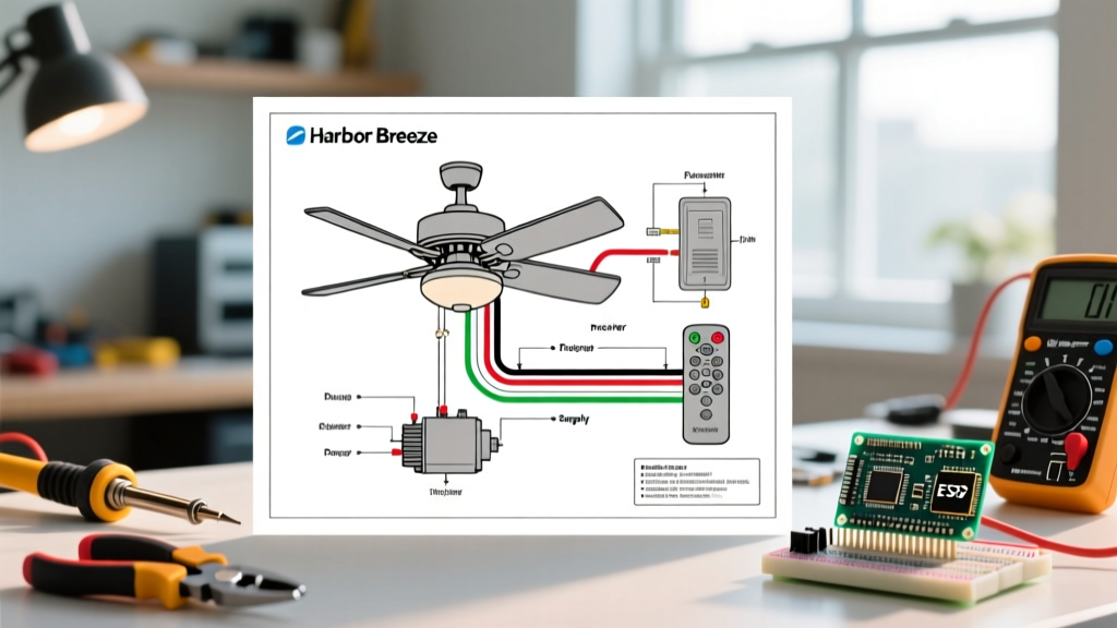

Understanding the Harbor Breeze Wiring Ecosystem
Harbor Breeze, the flagship ceiling fan brand sold exclusively through Lowe's, utilizes a standardized wiring architecture across most of its modern lineup, including popular models like the Merrimack, Armitage, and Breeze Pro series. Whether you are installing a new 52-inch model or troubleshooting an existing 60-inch smart fan, understanding the underlying wiring diagram is critical for safe operation and optimal performance.
As of 2026, Harbor Breeze has largely transitioned away from physical DIP switches on their remotes and receivers, opting instead for RF (Radio Frequency) learning sequences. This shift has simplified the physical wiring but introduced new troubleshooting nuances regarding signal pairing and canopy heat management. This comprehensive diagram reference will walk you through standard receiver installations, receiver bypass methods for dual wall switches, and internal motor capacitor wiring.
Standard Wire Color Code Matrix
Before making any connections, it is vital to identify the wire functions. Harbor Breeze fans typically use a standard color-coding scheme that interfaces with both the home's electrical supply and the included RF receiver module. Below is the definitive reference matrix for standard installations.
| Wire Source | Color | Function | Connection Point |
|---|---|---|---|
| House Supply | Black | Line / Hot (120V) | Receiver Black (AC IN) |
| House Supply | White | Neutral | Receiver White & Fan White |
| House Supply | Bare/Green | Ground | Mounting Bracket & Fan Green |
| Receiver Out | Black | Motor Hot | Fan Motor Black |
| Receiver Out | Blue | Light Kit Hot | Fan Light Kit Blue |
| Fan Motor | White | Motor/Light Neutral | House/Receiver White |
Scenario A: Wiring with the RF Receiver Module
The most common installation method involves routing the home's power through the Harbor Breeze receiver module, which sits inside the ceiling canopy. This allows the included handheld remote or wall-mounted RF transmitter to control both fan speed and light dimming independently.
Step-by-Step Receiver Wiring Procedure
- Prepare the Canopy: Ensure the ceiling electrical box is rated for ceiling fan support (minimum 35 lbs static, 70 lbs dynamic for larger models). The canopy depth on Harbor Breeze fans is typically 1.5 to 2.0 inches. You must neatly fold the receiver to avoid crushing the wires, which can cause thermal faults.
- Connect the Line and Neutral: Connect the house Black (hot) wire to the Receiver Black (AC IN) wire using a yellow wire nut. Connect the house White (neutral) to both the Receiver White and the Fan White wires using a red wire nut, as three wires are now joining.
- Connect the Loads: Connect the Receiver Black (Motor Out) to the Fan Black wire. Connect the Receiver Blue (Light Out) to the Fan Blue wire.
- Grounding: Connect the house bare copper ground to the fan bracket green screw and the fan's green ground wire. According to the National Electrical Code (NEC), all metallic fan components must be properly bonded to the equipment grounding conductor.
- RF Learning Sequence: Unlike older models, 2024-2026 Harbor Breeze receivers require digital pairing. Turn the breaker back on. Within 30 seconds of restoring power, press and hold the 'Learn' or 'Set' button on the receiver (or press a specific button combo on the remote, usually holding the 'Fan Off' and 'Light' buttons simultaneously for 3 seconds) until the fan lights flash or the motor jogs, confirming the pairing.
Scenario B: Bypassing the Receiver for Dual Wall Switch Control
Many homeowners prefer the tactile reliability of physical wall switches over RF remotes. If your home is wired with a 3-wire cable (14/3 or 12/3 NM-B) running from a dual switch box to the ceiling, you can completely bypass the Harbor Breeze receiver.
Wiring a Dual Switch Setup (e.g., Leviton 5641)
To achieve independent wall control for the fan motor and the light kit, you must remove the receiver from the canopy and wire the fan directly to the house supply.
- At the Ceiling Box: Remove the receiver entirely. Connect the House Black (Switch Leg 1 - Fan) directly to the Fan Black wire. Connect the House Red (Switch Leg 2 - Light) directly to the Fan Blue wire. Connect all White neutral wires together, and all Ground wires together.
- At the Wall Switch Box: Wire the incoming hot wire to the common terminal of your dual switch. Wire the Black load wire to the fan switch terminal, and the Red load wire to the light switch terminal.
Expert Warning: When bypassing the receiver, the fan will only operate at its highest speed when the wall switch is turned on. You will need to use the pull-chain on the fan motor housing to adjust the speed to medium or low. If you desire variable speed control from the wall without a remote, you must install a dedicated, hardwired solid-state fan speed control switch (such as a Lutron Maestro), ensuring it is specifically rated for ceiling fan motors and not just lighting dimmers.
Internal Motor Wiring: The CBB61 Capacitor Diagram
If your Harbor Breeze fan is humming but not spinning, or if it only operates on the 'High' speed setting, the wiring diagram you need to investigate is internal to the motor housing. The culprit is almost always a failed CBB61 run capacitor.
Harbor Breeze typically uses a 3-wire or 4-wire CBB61 capacitor (commonly rated at 5uF+5uF+5uF or similar microfarad combinations, operating at 250VAC). The capacitor wiring connects directly to the multi-tap windings of the AC induction motor.
- Wire 1 (Usually Black or L): Connects to the incoming hot line (from the receiver or wall switch).
- Wire 2 (Usually Gray or 1): Connects to the High-speed motor winding.
- Wire 3 (Usually Brown or 2): Connects to the Medium-speed motor winding.
- Wire 4 (Usually Purple or 3): Connects to the Low-speed motor winding.
Replacement CBB61 capacitors cost between $6 and $12 online. Always match the exact microfarad (uF) ratings and physical dimensions of the original part, as a mismatched capacitor will cause the motor to overheat and eventually fail.
Troubleshooting Common Wiring & Receiver Failures
Even with a perfect wiring diagram execution, environmental and component factors can cause operational issues. Here are the most common failure modes specific to Harbor Breeze systems:
1. Canopy Heat and Receiver Burnout
The RF receiver is a solid-state device that generates heat, especially when dimming LED bulbs or running the motor on medium speed. If the canopy is installed in an unventilated space or recessed too close to attic insulation, ambient temperatures can exceed the receiver's 60°C (140°F) rating. Symptom: The fan works intermittently, or you smell a faint ozone/plastic odor. Fix: Replace the burnt receiver (OEM replacements like the FAN-35T retail for $18-$25) and ensure the canopy has adequate airflow.
2. LED Flickering on Light Kit
Harbor Breeze receivers utilize TRIAC-based dimming circuits. If you install non-dimmable LED bulbs, or dimmable LEDs that are incompatible with leading-edge TRIAC dimmers, the lights will flicker or strobe. Fix: Use only bulbs explicitly labeled as "Compatible with TRIAC/CL Dimmers" or bypass the receiver's blue wire to provide unswitched 120V to the light kit, relying on smart bulbs for dimming control.
3. Signal Interference and Ghosting
If your Harbor Breeze fan turns on by itself, it is likely experiencing RF cross-talk from a neighboring unit operating on the same frequency (usually 303.8 MHz or 433.92 MHz). Fix: Perform a factory reset on the receiver by cutting power at the breaker for 60 seconds, then re-pair the remote using the unique learning sequence to establish a new digital handshake.
Safety and Code Compliance
Working with 120V AC mains requires strict adherence to safety protocols. Always verify that the circuit breaker is locked out and tagged out (LOTO) before opening the canopy or switch box. Use a non-contact voltage tester (NCVT) to confirm the absence of voltage on both the black and white wires.
Furthermore, ensure your electrical box is properly braced. The Electrical Safety Foundation International (ESFI) emphasizes that standard drywall anchors or light-fixture boxes are insufficient for the dynamic torque generated by ceiling fans. For comprehensive guidelines on energy efficiency and safe installation practices, refer to the ENERGY STAR Ceiling Fans specification sheet, which outlines maximum wattage limits and airflow efficiency standards that dictate proper wire gauge and circuit loading.
By following this wiring diagram reference and adhering to NEC standards, you ensure your Harbor Breeze ceiling fan operates safely, quietly, and efficiently for years to come.