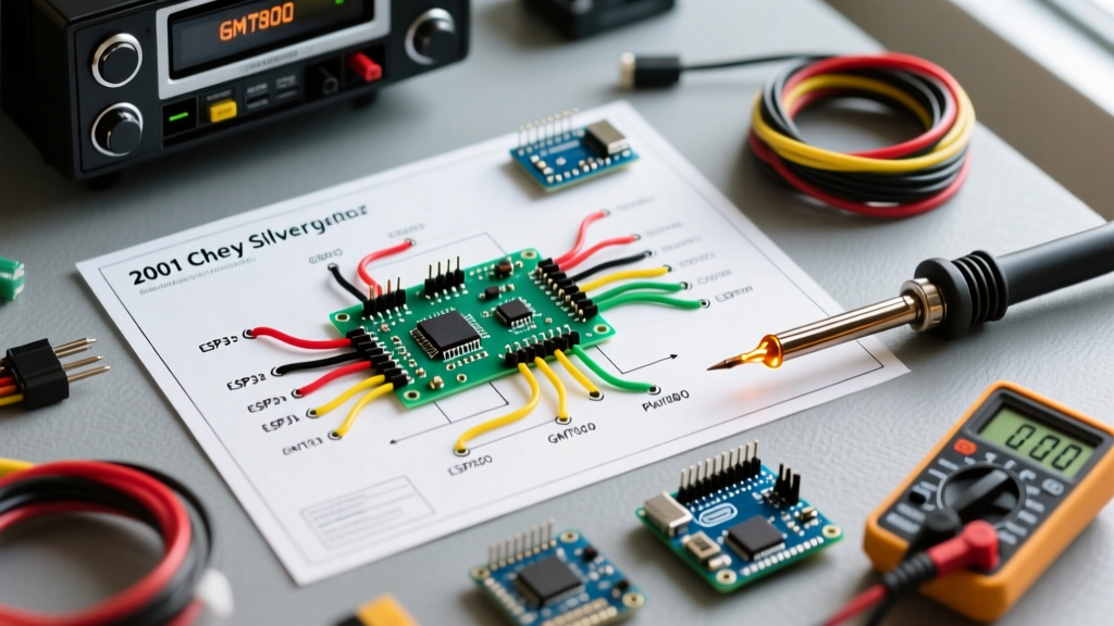

Understanding the GMT800 Audio Architecture
The 2001 Chevrolet Silverado, built on GM's robust GMT800 platform, represents a transitional era in automotive electrical systems. When upgrading to a modern aftermarket head unit—whether a high-end Alpine ILX-W65T or a budget-friendly off-brand Android unit—understanding the factory radio wiring diagram for the 2001 Chevy Silverado is critical. Unlike older vehicles that relied on simple analog 12V triggers, the 2001 Silverado integrates the radio with the Body Control Module (BCM) via the Class II Data Bus and Retained Accessory Power (RAP) circuits.
This comprehensive reference guide breaks down the exact pinouts, wire color codes, and integration modules required to successfully wire an aftermarket stereo without triggering dashboard error codes or losing premium audio functionality.
Standard 9-Pin Radio Wiring Diagram (Non-Amplified)
Base model 2001 Silverados (Work Truck, LS, and standard LT trims without the Bose badge) utilize a standard GM 9-pin connector. While the physical plug has 9 cavities, typically only 7 wires are populated. Below is the exact pinout mapped to the industry-standard Metra 70-1858 or equivalent wiring harness.
| Pin / Cavity | Wire Color | Function | Aftermarket Connection |
|---|---|---|---|
| A1 | Orange | +12V Constant (Battery Memory) | Yellow (Constant 12V) |
| A2 | Yellow | +12V Switched (Ignition/RAP) | Red (Switched 12V) |
| A3 | Black | Chassis Ground | Black (Ground) |
| A4 | Tan | Left Front Speaker (+) | White |
| A5 | Gray | Left Front Speaker (-) | White/Black Stripe |
| A6 | Light Green | Right Front Speaker (+) | Gray |
| A7 | Dark Green | Right Front Speaker (-) | Gray/Black Stripe |
| A8 | Brown | Left Rear Speaker (+) * | Green |
| A9 | Yellow (Stripe) | Left Rear Speaker (-) * | Green/Black Stripe |
* Note: Rear speaker wires may not be populated in the 9-pin harness on regular cab models. If you have rear speakers, your truck may use the 16-pin GM harness, which includes the rear channels (Brown/Yellow for LR, Dark Blue/Light Blue for RR).
The Bose Premium Audio Challenge: Class II Data Bus
If your 2001 Silverado is equipped with the Bose Premium Audio package, the standard wiring diagram above will not suffice. The Bose system utilizes an external amplifier (usually located under the center console or behind the rear seat in Crew Cabs) that does not use a standard 12V remote turn-on wire.
Why a Standard 12V Trigger Fails
GM's Class II Data Bus requires a digital handshake to wake the amplifier. If you attempt to wire a standard 12V remote turn-on lead from an aftermarket radio to the Bose amp, the amplifier will remain dormant, resulting in zero audio output. Furthermore, improperly tapping into the data line can throw U-codes (communication errors) in the BCM, potentially affecting your digital odometer and shift indicator.
The Solution: Data Bus Interfaces
To retain the Bose amplifier and factory subwoofer, you must install a Class II data interface module. As of 2026, the most reliable options include:
- Axxess GMR-01: Simulates the Class II data signal to turn on the amp and steps down the high-level Bose speaker outputs to low-level RCA pre-outs. (Approx. $75 - $90)
- Metra GMOS-01: Functions similarly but integrates directly with Metra's harness ecosystem. (Approx. $65 - $85)
Expert Warning: Never use 'T-taps' or 'scotch locks' on the GMT800 wiring harness. According to SAE International automotive wiring standards, piercing the insulation of modern automotive wire invites copper oxidation. Always use solder-seal heat shrink butt connectors or IPC-A-620 compliant crimping to prevent voltage drop and alternator whine.
Retained Accessory Power (RAP) & OnStar Edge Cases
The 2001 Silverado features Retained Accessory Power (RAP). This means the factory radio stays on after you turn the key off, until you open the driver's side door. When wiring an aftermarket radio, you have two choices for the switched 12V (Red wire) connection:
- True Ignition: Wire the aftermarket red wire to the yellow (switched) wire in the harness. The radio will turn off immediately when the key is removed.
- Retain RAP: Use a RAP retention interface (like the Axxess GMRC-01) which tells the aftermarket radio to stay on until the door opens, mimicking factory behavior.
The OnStar Complication
If your 2001 Silverado is equipped with OnStar, the audio prompts are routed through the driver's side front speaker via the factory radio. Unplugging the factory unit kills OnStar audio. To retain this feature, you must upgrade your interface to an OnStar-compatible model, such as the Metra GMOS-02 or Axxess GMR-02, which feature a dedicated OnStar audio override circuit.
Step-by-Step Dash Disassembly & Harness Access
Accessing the radio harness in the GMT800 dashboard is straightforward but requires care to avoid snapping aging 20-year-old plastic clips.
- Preparation: Disconnect the negative battery terminal (10mm wrench) to prevent shorting the dimmer circuit.
- Steering & Shifter: Tilt the steering wheel to its lowest position. Shift the transfer case into 4LO (if equipped) and the transmission into 1st gear to pull the PRNDL indicator out of the way.
- Bezel Removal: Firmly grasp the dash bezel surrounding the radio and climate controls. Pull straight outward. It is held entirely by friction clips.
- Radio Extraction: Locate the four 7mm hex-head bolts securing the radio brackets to the dash sub-frame. Remove them using a 7mm socket or nut driver.
- Disconnect: Slide the radio forward, depress the tab on the main 9-pin/16-pin harness, and unplug the Motorola antenna cable.
Common Wiring Failure Modes & Troubleshooting
Even with the correct radio wiring diagram for the 2001 Chevy Silverado, installers frequently encounter these specific GMT800 edge cases:
1. Alternator Whine (Ground Loop)
Symptom: A high-pitched whining noise that increases in pitch with engine RPM. Cause: The GMT800 dash frame is notorious for poor factory grounding due to paint overspray on the grounding bolts behind the dash. Fix: Do not rely on the factory radio ground wire alone. Run a dedicated 16 AWG ground wire from the aftermarket harness's black wire directly to a clean, unpainted metal bolt on the dashboard cross-brace.
2. Illumination / Dimmer Circuit Short
Symptom: Dash lights flicker, or the BCM blows a fuse when the headlights are turned on. Cause: The factory radio plug includes an Orange/White or Brown wire for the dash illumination dimmer circuit. Aftermarket radios often have an 'Orange' wire for illumination. If your aftermarket radio's dimmer wire draws too much current or shorts against the chassis, it will blow the BCM's interior lighting fuse. Fix: If you do not need the aftermarket radio's screen to dim with the headlights, simply cap off and isolate the factory dimmer wire and the aftermarket dimmer wire. Do not connect them.
3. Parasitic Battery Draw
Symptom: Truck battery dies after sitting for 3-4 days. Cause: Swapping the Constant 12V (Orange) and Switched 12V (Yellow) wires. If the radio's memory wire is connected to a constant 12V source but the radio's internal logic never receives the 'sleep' signal from the switched line, it will remain in a high-draw standby mode. Fix: Verify the Orange (Battery) and Yellow (Accessory) pins with a digital multimeter before making final connections.
Required Tools & 2026 Material Estimates
To execute this installation to professional standards, ensure you have the following tools and materials. Pricing reflects average 2026 market rates for quality automotive-grade components.
| Item | Specification | Estimated Cost |
|---|---|---|
| Wiring Harness Adapter | Metra 70-1858 (Base) or GMOS-01 (Bose) | $15 - $85 |
| Dash Kit | Metra 95-2000 (Double DIN) | $12 - $25 |
| Wire Strippers | 18-22 AWG Precision Strippers | $20 - $35 |
| Heat Shrink Tubing | Adhesive-lined, 3/16 inch | $10 - $15 |
| Panel Removal Tool | Nylon pry tool set (to save dash clips) | $8 - $12 |
For further technical documentation on GM Class II data protocols and aftermarket integration standards, refer to the engineering resources available at Metra Electronics. Properly interpreting the radio wiring diagram for your 2001 Chevy Silverado ensures a clean, reliable audio upgrade that respects the vehicle's original electrical engineering.