
Understanding the Basics: TRS vs. TRRS Pinouts
When repairing or custom-building audio cables, interpreting the correct wiring diagram for headphone jack connectors is critical. The 3.5mm audio connector is ubiquitous, but its internal pinout varies based on the number of poles and the governing industry standard. According to established phone connector standards, the physical rings on the plug correspond to specific audio channels and ground returns.
The TRS (3-Pole) Standard
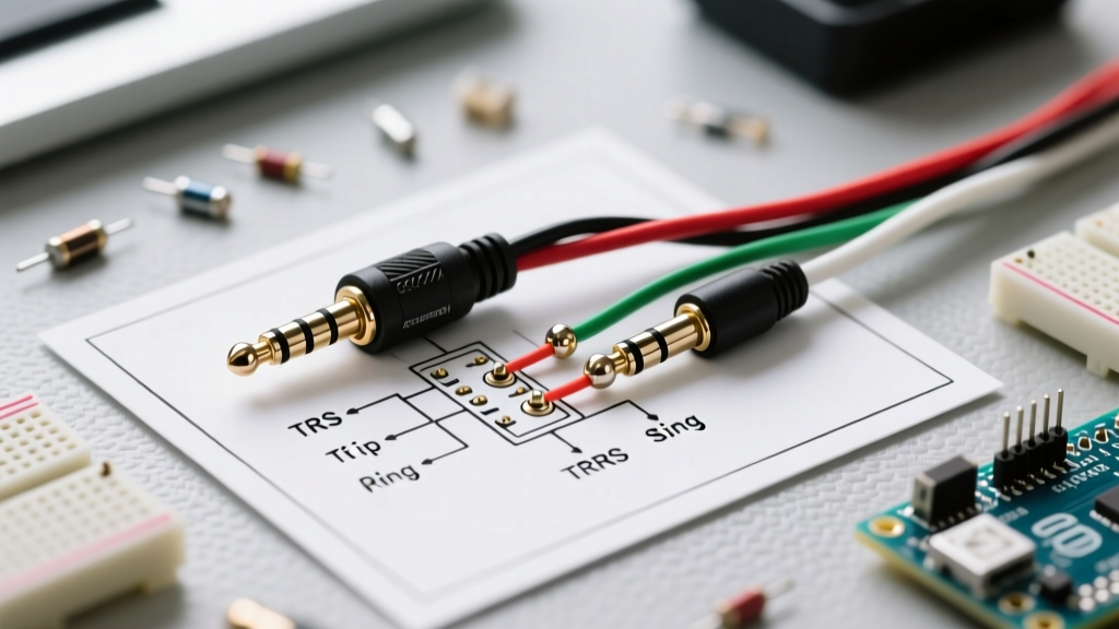
The Tip-Ring-Sleeve (TRS) configuration is the baseline for stereo audio without a microphone. It features three conductors:
- Tip: Left Audio Channel
- Ring: Right Audio Channel
- Sleeve: Common Ground
This is the standard used for most PC speaker outputs, studio monitor connections, and legacy portable audio devices.
The TRRS (4-Pole) Standard: CTIA vs. OMTP
When a microphone or inline remote is introduced, a fourth conductor is required, resulting in a Tip-Ring-Ring-Sleeve (TRRS) plug. However, the wiring diagram for headphone jack TRRS connections is split between two competing standards. Understanding the difference between TRS and TRRS configurations is vital to avoid phase cancellation and muted microphones.
| Pin Location | CTIA (AHJ) Standard | OMTP Standard |
|---|---|---|
| Tip | Left Audio | Left Audio |
| Ring 1 | Right Audio | Right Audio |
| Ring 2 | Common Ground | Microphone |
| Sleeve | Microphone | Common Ground |
Industry Note: CTIA (Cellular Telecommunications Industry Association) is the modern default, adopted by Apple, Samsung, Sony, and virtually all smartphones manufactured after 2012. OMTP is largely obsolete but still encountered in legacy Nokia and early Sony Ericsson devices.
Tools and Materials Required
To execute this wiring walkthrough reliably, you need professional-grade tools. Cheap irons will ruin the delicate PBT insulators inside the 3.5mm jack.
- Soldering Station: Weller WE1010NA or Hakko FX-888D (Must maintain stable thermal recovery).
- Solder: Kester 44 60/40 Sn/Pb Rosin Core (0.031" diameter). If lead-free is required, use SAC305 (Sn96.5/Ag3.0/Cu0.5) with a higher temperature profile.
- Flux: Kester 951 No-Clean Liquid Flux or Amtech NC-559-V2-TF.
- Connector: Switchcraft 35RAPC2 (TRS) or Neutrik NTP3RC-B (Panel Mount TRS).
- Wire Prep: Thermal wire stripper or fine-grit (800) sandpaper.
- Testing: Fluke 117 True RMS Multimeter (Continuity mode).
Step-by-Step Wiring Walkthrough
Step 1: Preparing Enamel-Coated Litz Wire
Most high-quality headphone cables use Litz wire—stranded copper individually coated in a thin polyurethane or polyesterimide enamel insulation. This enamel acts as a dielectric. If you simply wrap the wire around the jack lug and apply solder, the joint will fail because the solder cannot penetrate the enamel at standard temperatures.
The Fix: Set your soldering iron to 380°C (716°F). Apply a generous dab of liquid flux to the wire tip. Press the hot iron tip directly onto the wire and feed the solder. The high heat and flux will chemically burn off the enamel and tin the copper simultaneously in about 3 to 4 seconds. Wipe the iron tip on a damp cellulose sponge to remove the carbonized enamel residue.
Step 2: The Strain Relief and Shell (Do Not Skip)
The most common mistake in DIY audio wiring is soldering all connections perfectly, only to realize the jack's outer metal shell and heat-shrink tubing were not threaded onto the cable first. Always slide the rear housing, strain relief spring, and any heat-shrink onto the main cable before tinning your wires.
Step 3: Soldering the Connections
When soldering to the miniature lugs of a 3.5mm jack, thermal management is your biggest enemy. The internal dielectric block holding the lugs in place is typically made of PBT (polybutylene terephthalate) or ABS plastic, which has a relatively low melting point.
- Pre-tin the lugs: Apply a tiny amount of solder to the jack's Tip, Ring, and Sleeve lugs. Keep the iron contact time under 2 seconds per lug.
- Position the wire: Hold the tinned Litz wire against the pre-tinned lug using a third-hand tool or hemostat. Do not use your fingers; the heat transfers rapidly through the copper.
- Reflow: Touch the iron to the joint for 1.5 to 2 seconds. The pre-existing solder on both the wire and the lug should melt together into a smooth, shiny fillet.
- Inspect: A good joint looks like a miniature volcano. A dull, gray, or lumpy joint indicates a cold solder joint caused by insufficient heat or movement during cooling.
Step 4: Continuity and Short Testing
Before assembling the shell, you must verify the wiring diagram for headphone jack accuracy. Set your multimeter to the continuity/diode test mode (the setting that beeps).
- Probe the Tip wire and the Tip lug. You should hear a beep.
- Probe the Tip lug and the Ring lug. The multimeter should read "OL" (Open Line). If it beeps, you have a solder bridge (short circuit) between the left and right channels.
- Probe the Sleeve wire and the outer metal shell of the jack. It should beep, confirming a solid ground path.
Common Failure Modes and Troubleshooting
Even with a correct wiring diagram for headphone jack layouts, physical execution errors can cause audio anomalies. Use this matrix to diagnose issues:
| Symptom | Probable Cause | Technical Solution |
|---|---|---|
| Audio plays in mono, no stereo separation. | Left and Right channel wires are shorted together at the Tip and Ring lugs. | Use solder wick (Goot Wick) to remove excess solder and re-tin the lugs separately. |
| Vocals sound distant, hollow, or "underwater". | Ground (Sleeve) connection is broken, causing the left and right channels to play out of phase (Karaoke effect). | Reflow the Sleeve joint. Ensure the enamel on the ground Litz wire was fully burned off. |
| Microphone doesn't work, but audio is fine. | CTIA vs. OMTP mismatch, or Ring 2 and Sleeve are shorted. | Verify device standard. Clear any solder bridges between the two microphone/ground rings. |
| Jack feels loose or wobbles in the socket. | Excessive heat during soldering melted the internal PBT dielectric, shifting the lug alignment. | Replace the jack. Use a lower temperature (320°C for 60/40) and limit dwell time to 2 seconds. |
Expert Tips for Long-Lasting Audio Connections
To ensure your custom or repaired cables survive physical stress, apply a small drop of cyanoacrylate (super glue) or UV-curable solder mask over the exposed wire-to-lug joints after they have passed continuity testing. This provides secondary strain relief and prevents the fragile Litz wire from fatiguing and snapping right at the solder joint.
Finally, always use a high-quality heat-shrink tubing (like 3M or Alpha Wire) over the individual wire connections inside the barrel if the jack design permits. This prevents the bare wires from shifting and shorting against the interior of the metal shell during assembly, ensuring your wiring diagram for headphone jack execution remains flawless for years to come.